MEGApix® Flex™ 20MP user-configurable multi-sensor vandal dome IP camera with vari-focal lens pre-loaded with IVA+ DWC-PVX20WATW - IVA license pre-loaded DWC-PPVX20WATW- IVA+ license pre-loaded User’s Manual Ver. 03/22 Before installing and using the camera, please read this manual carefully. Be sure to keep it handy for future reference.
Safety Information Read this first Read through this Installation Guide carefully before installing the product. Keep the Installation Guide for future reference. See the complete user manual for more information on the proper installation, use and care of the product. These instructions are intended to ensure that users can use the product correctly to avoid danger or property loss.
Important Safety Instructions Precaution 1. Use proper safety gear when installing and wiring the product. 2. Do not drop objects on the product or apply strong shock to it. Keep away from a location subject to excessive vibration or magnetic interference. 3. Do not use this product near water. 4. The product shall not be exposed to dripping or splashing and no objects filled with liquids, such as vases, shall be placed on the product. 5.
Important Information Trademark acknowledgments Digital Watchdog, DW, DW Spectrum, MEGApix and Star-Light are registered trademarks or trademark applications of Digital Watchdog in various jurisdictions. Apple, Apache, Bonjour, Chrome, Ethernet, Internet Explorer, Linux, Microsoft, Mozilla, Real, SMPTE, QuickTime, UNIX, Windows, and WWW are registered trademarks of the respective holders. Java and all Java-based trademarks and logos are trademarks or registered trademarks of Oracle and/or its affiliates.
Table of Contents Introduction Product and Accessories......................................................................................................................................................................6 Parts Names......................................................................................................................................................................7 Installation Moisture Absorber Installation...................................................................
Introduction - Product & Accessories Camera RJ-45 Installation Tool Quick Setup and Download Guide Grommet SI PA PoE Injector K SI P DE Star Wrench Moisture Absorber and Installation Guide (Recommended) 6 Test Monitor Cable
Introduction - Part Name Dome Cover 4x SD Card Slots Reset Button Video Change Button Test Video Slot Network Port 7
Installation - Disassemble the camera Before installing your camera, please read the following cautions. 1 2 3 The mounting surface must be able to bear up to five times the overall weight of your camera. Avoid allowing cables to become pinched or abraded during installation. If the plastic wire jacket of the electrical line is damaged, it could result in an electrical short or fire.
Installation - Installation 1 Using the mounting template sheet for the mounting accessory, or the mounting accessory itself, mark and drill the necessary holes in the wall or ceiling. See the accessory’s QSG for more information. NOTE: A wall mount, ceiling mount, junction box, or in-ceiling flush mount are sold separately and are required to complete the camera’s installation. 2 Pass the wires through the mounting accessory and make all the necessary connections at the base of the camera.
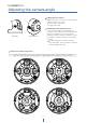
Installation - Adjusting the camera angle Tilting 80˚ 3 Rotation 350˚ 1 Adjusting the lens modules: Adjust the direction of each lens module while the camera is fixed on the ceiling. - Rotation angle is 350° total. - Tilt angle is 80° total. 2 Adjusting the monitoring field of view: - Once the lens modules are attached to the magnetic board, adjust the pan and tilting angles based on the direction you need to monitor.
Installation - Cabling 1. Network cable - to connect an RJ45 cable to the camera: Option A (recommended): a. Remove the grommet plug. b. Pass the network cable through the grommet at the base of the camera. c. Once the cables are through, add the RJ45 connector. a c b Option B: a. Attach the included RJ45 installation tool to the network cable. b. Remove the grommet plug. c. Pass the network cable’s connector through the grommet.
Installation - Cabling 1 Network Connection See page 11 for connection options. 2 Power A PoE injector is included with the camera. Please check the correct rated power. 5 3 1 2 - DC12V 2 + Power consumption DC12V, PoE IEEE 802.3bt PoE+ class 5 (High power PoE injector included) DC12V: max 28W PoE: max 31W Sensor/alarm input (DI) The sensor/alarm input device's cable should connect to + and - of the Terminal Block.
Installation - Managing the SD Memory Cards The camera supports up to four (4) individual SD cards. The memory card is an external data storage device that has been developed to offer an entirely new way to record and share video, audio, and text data using digital devices.
Network Setup - DW IP Finder™ Thumbnail view Firmware version Select network to scan Camera’s uptime Filter results Scan network Open IP configuration settings Show/hide thumbnail view Refresh thumbnail view Ping camera Bulk IP assignment Bulk password assignment Camera’s network information Firmware upgrade Camera’s name, IP and MAC addresses Selected camera’s username and password 1 To install the DW IP Finder, go to: http://www.digital-watchdog.
Web Viewer Screen - Basic Screen (Default) Password change is required at the initial connection in a factory reset state. The web client cannot be fully utilized until a new password has been assigned. 1 You cannot see the image, and the setup button is disabled. Create a new password, then click the CHANGE PASSWORD button. Password requirement: minimum 8-characters, using a combination of at least three (3) uppercase letters, lowercase letters, numbers, and special characters.
Web Viewer Screen - Basic Screen 2 1 3 4 5 6 7 8 1 Live video display. This is the region for the live video stream from the camera. 2 Setup popup button. Click to open the Setup page to setup details of the IP camera like Video, Network, Events, System, etc. See the section ‘Setup’. 3 Select Viewer. Click to open the live video display for separate lens modules or in a grid layout. 4 Live Buffering.
Setup - Video & Audio Setup Video Configuration 1 2 1 Detail Page - Select an item from the left navigation menu to view setup options on the main screen.
Setup - Video & Audio Setup Video Configuration 1 2 3 4 5 6 1 VIN Source - Each of the camera's sensors must be set up separately. Select between Video 1 ~ Video 4 for each of the camera's sensors. The settings below will apply to that sensor only. Click 'Apply' to save the settings before changing to another video source. 2 Live Video Channel Setup - The video can be configured to various settings with a combination of codec and resolution.
Setup - Video & Audio Setup Video Configuration 7 8 9 6 GOP (Group of Pictures) Size - Set the number of frames (P-frame) which contain only changed information based on the basic frame (I-frame). For videos with lots of movement, set the GOP value higher to capture more P-frames. In this case, the video resolution will be lower but ‘File size’ and ‘Bit-rate' can decrease. GOP (Group of Pictures) Size ‘I-frame’, also known as ‘key-frame’, refers to the complete image data for a specific video frame.
Setup - Video & Audio Setup Video Configuration 10 11 12 13 14 10 Target Bitrate - Set the target bitrate when Bitrate Control is set to CBR. 11 Quality - Set the target quality for video when Bitrate control is set to VBR. 12 Smart Bitrate Control Off - Smart Bitrate Control is disabled. CVBR (Framerate priority) - Enable this option when users do not want any frame drop and no lower bitrate.
Setup - Video & Audio Setup OSD Configuration 1 2 3 4 1 VIN Source - Each of the camera's sensors must be set up separately. Select between Video 1 ~ Video 4 for each of the camera's sensors. The settings below will apply to that sensor only. Click 'Apply' to save the settings before changing to another video source. 2 Date / Time - Display the current time over the live image from the camera. 3 User Text - Display TEXT set up by users. Text can be a maximum of 30 characters.
Setup - Video & Audio Setup Region of Interest Configuration 1 2 3 4 5 The region of interest function gives a much more efficient picture quality for the target area to improve movement picture quality using the same bandwidth. 1 VIN Source - Each of the camera's sensors must be set up separately. Select between Video 1 ~ Video 4 for each of the camera's sensors. The settings below will apply to that sensor only. Click 'Save' to save the settings before changing to another video source.
Setup - Video & Audio Setup Audio Configuration 1 2 3 4 1 Codec - Select the Audio Codec. Currently, the camera supports only codec G.711. 2 Volume - Select the Audio Volume from 0 to 10. To use camera audio, a value greater than 0 must be applied for the Volume setting. 3 Sample Rate - Select the Audio sample rate. Currently, it supports only 8000 Hz. 4 Click ‘Save’ to save the current settings.
Setup - Video & Audio Setup Privacy Mask Configuration 1 2 3 4 Use this function to mask areas that you want to hide on the screen to protect user privacy. 1 2 VIN Source - Each of the camera's sensors must be set up separately. Select between Video 1 ~ Video 4 for each of the camera's sensors. The settings below will apply to that sensor only. Click 'Save' to save the settings before changing to another video source. Activation - Enable or disable the privacy masks function.
Setup - Camera Setup MFZ Configuration 1 2 3 1 Zoom and Focus - Zoom OUT (-) or zoom IN (+) and focus OUT (-) or focus IN (+) each camera module. Focus button (-) / (+) is activate in manual mode. 2 Zoom Speed - Set the zoom and focus speed from 1~3. 3 Auto and Manual - Toggle between the Auto and Manual buttons to switch settings mode. Auto mode - Auto focus is activated once the zoom (-) / (+) action is completed. Auto focus is activated once and the focus button (-) / (+) is disabled.
Setup - Camera Setup Camera Image Adjustment 1 2 3 4 5 6 7 1 VIN Source - Each of the camera's sensors must be set up separately. Select between Video 1 ~ Video 4 for each of the camera's sensors. The settings below will apply to that sensor only. Click 'Save' to save the settings before changing to another video source. 2 Sharpness - Adjust the sharpness of the image as needed. 3 Brightness - Adjust the brightness of the image as needed.
Setup - Camera Setup Camera Exposure Settings 1 2 3 4 5 6 7 8 9 1 VIN Source - Each of the camera's sensors must be set up separately. Select between Video 1 ~ Video 4 for each of the camera's sensors. The settings below will apply to that sensor only. Click 'Save' to save the settings before changing to another video source. 2 Auto Exposure - Automatically sets the aperture or shutter speed, based on the external lighting conditions for the camera.
Setup - Camera Setup Camera Day & Night Settings 1 2 3 4 5 6 1 VIN Source - Each of the camera's sensors must be set up separately. Select between Video 1 ~ Video 4 for each of the camera's sensors. The settings below will apply to that sensor only. Click 'Save' to save the settings before changing to another video source. 2 Day & Night - Auto: The IR cut filter is added or removed automatically based on the lighting conditions.
Setup - Camera Setup Camera Backlight Settings 1 2 3 4 This is a feature used for problematic light conditions where the contrast from light to dark areas is very high. 1 VIN Source - Each of the camera's sensors must be set up separately. Select between Video 1 ~ Video 4 for each of the camera's sensors. The settings below will apply to that sensor only. Click 'Save' to save the settings before changing to another video source.
Setup - Camera Setup Camera White Balance 1 2 3 4 5 1 VIN Source - Each of the camera's sensors must be set up separately. Select between Video 1 ~ Video 4 for each of the camera's sensors. The settings below will apply to that sensor only. Click 'Save' to save the settings before changing to another video source. 2 Activation - Enable or disable the white light settings.
Setup - Camera Setup Camera Image Enhancement 1 2 3 4 5 1 VIN Source - Each of the camera's sensors must be set up separately. Select between Video 1 ~ Video 4 for each of the camera's sensors. The settings below will apply to that sensor only. Click 'Save' to save the settings before changing to another video source. 2 3D Noise Reduction - Reduce digital noise (image graininess) in the image while retaining good video quality in low light conditions. The default value is 5.
Setup - Camera Setup Video Enhancement 1 2 3 1 VIN Source - Each of the camera's sensors must be set up separately. Select between Video 1 ~ Video 4 for each of the camera's sensors. The settings below will apply to that sensor only. Click 'Save' to save the settings before changing to another video source. 2 Flicker - When the camera suffers any flickering issues, adjust the settings to improve the image quality. 60Hz - NTSC (North America, Japan, etc.) 50Hz - PAL (UK, Europe, etc.
Setup - Network Setup Network Status This menu shows the current network settings for the camera. To edit any settings, select the "Network Settings" submenu.
Setup - Network Setup Network Settings 1 2 3 4 5 6 7 8 9 10 1 Network Type - Define the network IP address type. Select Static Mode for a fixed IP or Dynamic Mode for a dynamic IP address. If you select Static Mode, enter the camera's IP Address, Subnet Mask, Gateway, DNS Server and all ports. If you select Dynamic Mode, the IP address will be assigned automatically by the DHCP network requirements.
Setup - Network Setup Auto IP Settings 1 2 3 1 General Setting - Enable or disable the Auto IP Settings. 2 Auto IP Settings Information - Display the camera's Unique ID and Auto IP address. The camera can resort to using its Auto IP Address if a DHCP (dynamic) or a static IP address cannot be provided. 3 Click ‘Apply’ to save all settings.
Setup - Network Setup ONVIF Settings 1 2 3 1 Authentication ONVIF authentication allows the camera to be automatically and securely discovered on local networks by ONVIF-compliant devices. None: Allow access to the camera without ONVIF authentication. WS - Usertoken: Allow access to the camera with WS-User Token of ONVIF authentication. WS - Usertoken + Digest: Allow access to the camera with WS-User Token and Digest of ONVIF authentication. 2 Discovery Mode - Enable or disable discovery mode.
Setup - Network Setup UPNP Settings 1 2 3 1 2 3 General Setting - Enable or disable the UPNP function. Universal Plug and Play (UPnP) allows the camera to automatically set port access rules for itself for communication with other compliant network devices. Friendly Name - Define the friendly name. Support a maximum of 30 characters and special characters. • Do not use: / ~ ! $ ( ) { } [ ] ; , • Acceptable special characters include; @ . _ Click ‘Apply’ to save all settings.
Setup - Network Setup DDNS Settings 1 2 3 1 DDNS Disable - When disabled, the camera will not use DDNS addressing. 2 Public DDNS - To use public DDNS service, select a site address listed on the list. After filling out the Host Name of the site the setup is completed by entering the username and password registered on that DDNS site. DDNS Provider Site Address DynDNS www.dyndns.com No-IP www.no-ip.
Setup - Network Setup FTP Settings 1 2 3 4 5 6 7 To transfer/save the image to the relevant sites through FTP, then FTP needs to be setup. 1 General Setting - Enable or disable the FTP function. 2 FTP Server Address - Define FTP Server IP Address. If the IP Address form is incorrect, a message box will be shown to try again. 3 FTP Upload Path - Define a path in FTP server to store video.
Setup - Network Setup SMTP Settings 1 2 3 4 5 6 7 8 9 10 11 12 To send/save the image to the relevant sites by Email, SMTP needs to be setup. 1 General Setting - Enable or disable the SMTP function. 2 Mode - Select the security mode of SMTP from Plain or SSL / TLS. After checking the account setup of your SMTP Server, you may select one. 3 SMTP Server Address - Define the SMTP Server Address. If the IP Address form is incorrect, a message box will be shown to try again.
Setup - Network Setup SNMP Settings 1 2 3 4 5 6 7 8 9 10 11 For use with administrative computers (managers) to monitor devices on a computer network, Simple Network Management Protocol (SNMP) settings can be applied to the camera. 1 SNMPv1/SNMPv2 - Select the SNMPv1/SNMPv2 option and type the names of Read and Write communities. SNMP trap can be used to check periodically for operational thresholds or failures that are defined in the MIB. 2 SNMP Trap - Enable or disable the SNMP trap.
Setup - Network Setup HTTP Action 1 2 3 4 1 General Setting - Enable or disable the camera to send out an HTTP action when an event occurs. When enabled, the camera can notify a monitoring software using HTTP protocol. 2 Account information - Set the RTSP time out. Description: Enter a short description to be HTTP Action Server: Enter the HTTP address of the receiving server. This is the server that will receive the HTTP action notification from the camera.
Setup - Network Setup RTSP Information 1 2 3 4 5 6 7 1 VIN Source - Each of the camera's sensors must be set up separately. Select between Video 1 ~ Video 4 for each of the camera's sensors. The settings below will apply to that sensor only. Click 'Apply' to save the settings before changing to another video source. 2 Target Stream - Select the stream you want to set. 3 Time out - Set the RTSP time out. The session is disconnected after the specified time-out.
Setup - Trigger Action Setup Action Rules Configuration 1 2 1 Action rules List - It indicates the custom action rule information added to the Action rules list. 2 Click ‘Add’ to add custom action rules. Click ‘Modify' to modify selected items from the action rules list. Click 'Delete' to delete selected items from the action rules list.
Setup - Trigger Action Setup Action Rules Add / Modify 1 2 3 1 Name - Define the name of the action rules. Input text cannot exceed the limit (3~15 characters). 2 Action1 ~ Action5 - Select the action to take If the event occurs. 3 Click ‘Save’ to save all settings. Click 'Cancel' to return to the previous menu.
Setup - Trigger Action Setup Image Transfer Configuration 1 2 1 Pre/Post Alarm Image - Image Transfer due to event is configured by setting the image transfer rate and Pre/Post alarm duration. Descriptions 2 Number of Images Define the number of images transferred per second. Pre-alarm Duration Define the duration of image transfer before an event. Post-alarm Duration Define the duration of image transfer after an event. Click ‘Apply’ to save all settings.
Setup - Trigger Action Setup Relayout Configuration 1 2 3 4 5 1 Relay Output - Select the Relay output. The number of relay outputs available depends on the camera model. 2 Mode - Select the monostable/bistable for relay mode. 3 Idle State - Select whether the contact is normally opened or is closed. 4 Duration - Relay out is operated during the setting time. In monostable mode, this function must be set up. 5 Click 'Apply' to save all changes.
Setup - Event Setup Event Rules Configuration 1 2 1 Event Rules List - It indicates the custom Event Rule information added to the Event Rules list. 2 Click ‘Add’ to add custom event rules. Click ‘Modify' to modify selected items from the event rules list. Click 'Delete' to delete selected items from the event rules list.
Setup - Event Setup Event Rules Configuration 1 2 3 4 1 Name - Enter a name for the new event rule. 2 Event - Select the event to trigger the rule. Select from motion detection, network disconnection, illegal login detected, temperature critical, sensor detection, or system initialize. Click 'Cancel' to return to the previous setting. You need at least one event. 3 Rules - Select the action to take when the event rule has been activated/triggered.
Setup - Event Setup Motion Detection Configuration 1 2 3 4 5 6 1 Motion Detection - Shows the Motion event status. The event alert icon ( ) will appear, indicating motion in the highlighted sensor. 2 VIN Source - Each of the camera's sensors must be set up separately. Select between Video 1 ~ Video 4 for each of the camera's sensors. The settings below will apply to that sensor only. Click 'Apply' to save the settings before changing to another video source. 3 Area - Set the motion detected area.
Setup - Event Setup Temperature 1 2 3 4 1 Mode - Select Fahrenheit or Celsius. 2 Threshold - Define the temperature at which the event trigger occurs. 3 Temperature - It indicates the current temperature of the IP camera. 4 Click ‘Apply’ to save all settings.
Setup - Event Setup Alarm Configuration 1 2 1 Input Device Setup - Select input device type from OFF / N.O. / N.C. Operation 2 OFF Ignore this input sensor. NO The contact is normally open and closed when activated. NC The contact is normally closed and open when activated. Click ‘Apply’ to save all changes.
Setup - Record Setup Record Management 1 2 3 4 1 Target Stream - Select the channel you want to record video. An SD card is required for each lens module to locally record. 2 Click ‘Save’ to save the current settings. 3 Recording List - Display the information about the recording settings. 4 Click ‘Modify’ to modify the selected item in the recording list.
Setup - Record Setup Record Configuration 1 2 3 4 5 6 7 8 1 Enabled - Enable or disable this function. 2 Storage Device - This option shows the SD card currently mounted on the camera. The camera supports up to four (4) SD cards, each assigned to one lens module. When recording, each SD card will record video only from the lens module assigned to it. 3 File Type - Select the recording file type. Currently, the camera supports MP4 file type. 4 Storage - Select the storage type.
Setup - Record Setup Recording List 1 2 3 4 5 1 Storage - Select the Storage from the available options. The camera supports up to four (4) SD cards, each assigned to one lens module. When recording, each SD card will record video only from the lens module assigned to it. 2 Filter - Select the date/time, event, sort, or storage format to filter the recorded video results. 3 Click the 'Refresh' button to refresh the search results as needed. Click 'Filter' to view the filtered recorded video.
Setup - Record Setup Recording Video 1 2 3 1 Recording Video Viewer - Play the recorded video. 2 Recording Video Information - Display information about the recorded video. 3 Click 'Replay' to view the recorded video again. Click 'Back' to return to the previous menu.
Setup - Record Setup Storage Configuration Display the SD card information mounted on the device. Each item in the list represents one of the four (4) SD cards the camera supports, showing the mounting status, size, percentage used and available storage.
Setup - Record Setup Storage Configuration 1 2 3 4 5 6 1 Storage Size - Total capacity of SD card and the remainder of it are displayed. 2 Auto Delete - Select the period for auto delete. The data stored before the set period will be deleted automatically. Delete all stored images older than the selected time. 3 Overwrite - If ON is selected, once the SD card has less than 8MB of storage available, new data will start to overwrite the oldest data.
Setup - Security Setup IP Address Filter Configuration 1 2 3 4 5 6 1 IP Address Filter - Enable or disable this function. 2 IP Filter Type - Select whether to allow or deny network data packets with the specified IP address. 3 Click ‘Apply’ to save all settings. 4 Filter IP Address - Display the filtered IP address. 5 IP Address - Define the IP address you want to apply the IP filter. 6 Click ‘Add’ to add the IP address to the list.
Setup - Security Setup RTSP Authentication Configuration 1 2 1 RTSP Authentication - Enable or disable the RTSP authentication. 2 Click ‘Apply’ to save all settings.
Setup - Security Setup IEEE 802.1X Configuration 1 2 3 4 5 6 7 8 9 The feature is needed when connecting the camera to the network protected by the IEEE 802.1X. IEEE 802.1x - Enable or disable the IEEE 802.1x feature. 1 2 • • • • Protocol MD5: It provides one-way password-based network authentication of the client. PEAP: It is similar to TTLS in that it does not require a certificate on the client-side. TTLS/MD5: It does not require a certificate on the client-side.
Setup - Security Setup HTTPS Configuration 1 2 3 HTTPS encrypts session data over SSL or TLS protocols instead of using plain text in socket communications. 1 2 3 Certificate - Select an installed certificate. If you cannot select a certificate, please install the certificate from the Security->Certificates menu. HTTPS connection Policy - Select one of “HTTP”, “HTTPS”, “HTTP and HTTPS” depending on the connected web, ONVIF, RTSP over HTTP.
Setup - Security Setup Certificates Configuration 1 3 2 4 5 6 7 9 8 10 1 Server/Client Certificates - Shows the installed certificates. 2 Create Self-Signed Certificate - A self-signed SSL certificate is an identity certificate signed by its creator. But they are considered to be less trustworthy. 3 Properties - Shows information about the selected certificate. 4 Delete - Delete the selected certificate.
Setup - Security Setup Certificates Configuration 1 3 2 4 5 6 7 8 10 9 Detail for Install Certification. 1 Certificate From Signing Request - Select to install a signed certificate returned from the CA. 2 Certificate And Private Key - Select to install Certificate And Private Key to install a certificate and private key. 3 Certificate Name - Enter a unique name to identify a certificate. 4 Select File - Choose the certification file. 5 OK - Request installing a certificate.
Setup - Security Setup Auto-Lock Configuration 1 2 1 Auto Lock - Enable or disable the function. When enabled, the system will lock itself for five (5) minutes after three (3) failed login attempts. 2 Click ‘Apply’ to save all settings.
Setup - System Setup System Information 1 2 3 System Capability information. 1 Device Name - Enter the device's name. 2 Location - Enter the device's location. 3 Click ‘Apply’ to save all settings.
Setup - System Setup System Diagnostics 1 Shows basic hardware functions after inspection. 1 Shows Uptime, SD card, NAND, EEPROM, Audio chip, Important file system and NTP Status. Warning: If the camera is abnormally terminated, a download button will appear on the diagnostics page to download a file that allows you to check the error information you can.
Setup - System Setup Configuration Backup 1 2 Use this page to import or export the camera settings. 1 Select to download or upload camera settings. The following settings are NOT included in the backup files: Network (except RTSP information), System > user management, PTZ settings (on PTZ models). Download: save the camera's current settings. Check the box next to 'Download', enter a backup key and click APPLY. The backup key can be of any value.
Setup - System Setup Firmware Update 1 2 3 1 Version Information - It shows the current Firmware Version in the system. 2 Web Update - Select the Firmware file on your computer by clicking the [Select file] button. 3 Start F/W Update - Click this button to start the update. Progress of uploading will be displayed using Progress Bar. If you assign the wrong file name, an error message will be shown. Warning: 1. Do not turn off the power to the camera during the firmware update.
Setup - System Setup Date & Time Settings 1 2 3 4 5 6 7 1 TimeZone Setup - Choose the time zone for the camera. It will be activated after clicking the ‘Apply’ button. Before setting below ‘New Camera Date and Time’, set the correct time zone first. 2 Time Format - Select the time format yy-mm-dd or mm/dd/yy. 3 Current Date and Time - Current date and time setting in the Camera. 4 Synchronize with my computer - Set the date/time using those of the PC currently connected.
Setup - System Setup DST Settings 1 2 3 Daylight Saving Time (DST) is the practice of setting the clocks forward one hour from standard time during the summer months and back again in the fall to make better use of natural daylight. 1 General Setting - Enable or disable the DST function. 2 Date and Time Settings - Set the start time and end time that the DST applies. 3 Click ‘Apply’ to save all settings.
Setup - System Setup Users Management 1 2 1 Users - List all the user accounts for authentication. 2 Add - Register a new user. ID Password Verify User Authority 3 4 Enter a new user ID except for Admin. Enter a password for the new user Enter the user password again for verification. Select the user type from 'Operator' or 'Viewer'. Viewer: Can view video from the camera. Operator: Can view video from the camera and access most of the camaera functions except for the ‘Setup’ menu.
Setup - System Setup System Log 1 2 3 1 Filter - Select a date, time, sort, or type of log to filter the log. 2 Click the 'Refresh' button to refresh the log list. Click 'Filter' to view the filtered log. Click 'Backup' to back up the filtered log. 3 System Log List - The filtered log is displayed.
Setup - System Setup Factory Reset 1 2 1 Reset to the factory defaults - Return the setup to the factory default. All - Reset all camera settings to their factory default. Except Network Settings and User Settings - Reset all camera settings to factory default except for the Network and User settings. 2 Click ‘Apply’ to save all settings.
Setup - System Setup Restart If you click the ‘RESTART’ menu, a message box will be shown to confirm. Click the ‘OK’ button to restart.
Setup - System Setup System Open Source License This menu shows a list of all the System Open Source License information in the camera, including Open Source Name, Version, License, etc.
Setup - System Setup Plug-In 1 2 3 4 5 1 Plug-in List - View all plug-ins currently installed on the camera. 2 Configuration - Show the settings for the selected plug-in from the list. Start/Stop - Start/stop the selected plug-in from the list. Uninstall - Remove the selected plug-in from the list. Logs - Download the log file for the selected plug-in from the list. 3 Information - View additional information for the plug-in selected from the list.
Network Setup - Quick Start of Network Connection 11 Access your IP Camera via the Internet (from a different network from the one your camera is): Follow the steps below to complete the initial network setup. If you use a static IP address assigned by your ISP: 1. Open Internet Explorer. 2. Type the address of the IP camera. 3. If you use a router, enter the router's static IP and the web port number of the IP camera. i Do not power on the IP camera until instructed.
Network Setup - DDNS Registration If you have a DYNAMIC IP service from your Internet Service Provider (ISP), you cannot tell the current IP address of the IP Camera. To solve this problem, you must register with our DDNS service. First, you must check if you are using dynamic addressing. If so, register your IP Video Server on our DDNS website before you configure, setup, or install the IP Camera. Even though your IP is not dynamic, you will benefit by registering your device with a DDNS service.
Network Setup - Guide to the Network Environment Please configure the IP Camera at the installation site. You must determine your network scenario to configure the IP Camera with the proper TCP/IP settings. This tutorial will guide you through the process. Before actually configuring the IP Camera, determine the settings to be applied. Record those settings to be used to configure your IP Camera for reference. When configuring your IP Camera, treat the IP Camera as another PC on your network.
Network Setup - Setup Case A, B Case A: Dynamic IP + Personal Router [Most SOHO] Configure your IP Camera’s TCP/IP properties: Camera 1 Network Type: STATIC (even though you have Dynamic IP from your ISP, use STATIC on the IP camera). 2 Internet Address: A private IP address such as 192.168.0.200 (example) i You need to assign an IP address to the IP Camera just PC as you do with PC.
Network Setup - Setup Case C, D Case C: Static(Fixed) IP [Dedicated line directly to the IP Camera] Case D: Dynamic IP + DSL/Cable Modem [Connected directly to the IP Camera] Camera Camera Cable/xDSL Modem (ISP Provided) Gateway or Router at ISP Phone Line or CATV Public Line Internet Internet i To connect the IP Camera directly to a modem, power down and reset the modem.
Network Setup - Port Forwarding After entering the correct TCP/IP settings, you are ready for ‘Port Forwarding’ (Cases A, B). Use the table below to note your camera's TCP/IP settings for future reference. You may need this information to access your IP Camera and to configure ‘port forwarding’. 1 IP camera TCP/IP settings IP address Subnet mask Default gateway Preferred DNS server DDNS server Web port 2 After clicking ‘Apply’, the system will prompt for a reboot.
Network Setup - Starting IP Camera After forwarding correctly the Web Port, through your router (if applicable), install the IP Camera in a proper location. 1 Locate the serial number located on the label attached to the bottom of the IP camera, you will need this for DDNS registration. 2 Connect the IP Camera to your router or cable/ DSL modem (per your network scenario) via a Cat5/5e UTP Ethernet network cable. 3 Supply power to the IP camera.
Appendix FAQ 1. My POWER light is not on? 8. How do I “PING” an IP address? Power is not being supplied to the unit. Please use the 1) Open an MS-DOS (or Command) prompt power supply shipped with the unit and verify that a 2) At the prompt type - “ping xxx.xxx.xxx.xxx” (without the power source is active from the attached power outlet quotes and replace the “x” s with an IP address) used to connect the adapter.
Specifications - Dimension Unit: inches (mm) ø8.26" (ø210mm) 1.76" (44.8mm) 4.5" 3.61" (114.3mm) (91.
Specification - Spec. CAMERA I/O AND EVENT Image sensor 4x 1/2.8” 5.14M CMOS Audio in/out 1 (1.0Vms, 3K ohm) in/1 out Total pixels 4x 2592(H) x 1944(V) Alarm in/out 1 in/1 out Focal length 2.8 ~ 8.0mm, F1.6 / MFZ Horizontal angle D: 64°~119°, H: 51°~93°, V: 39°~68° Video output (2nd video out) 1 (CVBS 1.0V p-p 75Ω), 4:3 aspect ratio Event notification FTP, email, alarm out, SD card Shutter speed Auto, manual (1/15 ~ 1/32000), anti-flicker, slow shutter (off, 2X, 3X, 5X, 6X, 7.
Warranty Information Go to https://digital-watchdog.com/page/rma-landing-page/ to learn more about Digital Watchdog’s warranty and RMA. To obtain warranty or out of warranty service, please contact a technical support representative at: 1+ (866) 446-3595, Monday through Friday from 9:00 AM to 8:00 PM EST. A purchase receipt or other proof of the date of the original purchase is required before warranty service is rendered.
Limits and Exclusions There are no express warranties except as listed above. The Warrantor will not be liable for incidental or consequential damages (including without limitation, damage to recording media) resulting from the use of these products, or arising out of any breach of the warranty. All express and implied warranties, including the warranties of merchantability and fitness for a particular purpose, are limited to the applicable warranty period set forth above.
DW® East Coast office and warehouse: 5436 W Crenshaw St, Tampa, FL USA 33634 DW® West Coast office and warehouse: 16220 Bloomfield Ave, Cerritos, CA USA 90703 PH: 866-446-3595 | FAX: 813-888-9262 www.Digital-Watchdog.com dw-tech@digital-watchdog.com Technical Support PH: USA & Canada 1+ 866-446-3595 International 1+ 813-888-9555 French Canadian: + 1-904-999-1309 Technical Support Hours: Monday-Friday 9 a.m. to 8 p.m.