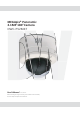
MEGApix® Panoramic 2.1MP 180° Camera DWC-PV2M4T User’s Manual Ver. 1.0 / 2015.04.21 Before installing and using the camera, please read this manual carefully. Be sure to keep it handy for future reference.
Safety Information CAUTION RISK OF ELECTRIC SHOCK. DO NOT OPEN. CAUTION: TO REDUCE THE RISK OF ELECTRIC SHOCK, DO NOT REMOVE COVER (OR BACK) NO USER SERVICEABLE PARTS INSIDE. REFER SERVICING TO QUALIFIED SERVICE PERSONNEL. Warning Precaution This symbol indicates that dangerous voltage consisting a risk of electric shock is present within this unit.
Important Safety Instructions 1. Read these instructions. - All these safety and operating instructions should be read before the product is installed or operated. 2. Keep these instructions. - The safety, operating and use instructions should be retained for future reference. 3. Heed all warnings. - All warnings on the product and in the operating instructions should be adhered to. 4. Follow all instructions. - All operating and use instructions should be followed. 5. Do not use this device near water.
Disposal of Old Appliances 1. When this crossed-out wheel bin symbol is attached to a product it means the product is covered by the European Directive 2002/96/EC. 2. All electrical and electronic products should be disposed of separately form the municipal waste stream in accordance to laws designated by the government or the local authorities. 3. The correct disposal of your old appliance will help prevent potential negative consequences for the environment and human health.
Introduction - Product & Accessories Please check that all the following accessories are included in the package.
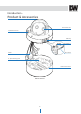
Introduction - Product & Accessories 3 Panoramic Lens Tilt,Rotation Control OSD Cap Main Body Cables Reset Button SD card Slot ¾” Pipe Mounting Hole Hard Lock Set Screw Mount Bracket 5
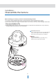
Installation - Disassemble the Camera Before installing your camera, you have to read the following cautions. 2. Don’t let the cable to be caught in improper place or the electric line cover to be damaged. Otherwise 3. When installing your camera, don’t allow any person to approach the installation site. If you have any valuable things under the place, move them away.
Installation Mounting the Camera 1 Disassemble the camera, See the section ‘Disassemble the camera’ for details. 2 Using the template sheet, make the cabling holes on the wall/ceiling. 3 Fix the Mount bracket on the wall/ceiling by screw provided. 4 Hook the Main body to Mount bracket with safety wire. S Bring the cables into the Mount bracket through the hole. Template Sheet 2 3 Safety Wire Mount Bracket Hole 4 S 6 7 8 7 6 Connect the cables respectively.
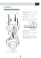
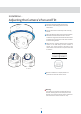
Installation - Adjusting the Camera's Pan and Tilt Lens Tilt 6 Pull wires through and make all necessary connections. See 'Cabling' section for more information. 7 Connect the camera's main body to the mounting bracket. 8 Adjust the panning angle of the camera and tighten hard lock set screw to fix the camera. Use the included six-angle wrench included with the camera to tighten the screw and secure the camera module to the mounting bracket.
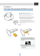
Installation Inserting / Removing the SD Memory Card 1 To open the SD card slot, use the included Torx wrench. 2 Insert the SD card in the arrow direction. Do not insert the SD memory card while it’s upside down by force. Otherwise, it may damage the SD memory card. 3 Removing an SD Memory Card Gently press down on the Remove the SD Memory Card gently by pressing down on the exposed end of the memory card as shown in the diagram to eject the memory card from the slot.
Installation - Cabling White: DIN+ Yellow: DINBlack: DOUTRed: DOUT+ 4 Alarm In 3 Alarm Out 2 Audio In 1 Audio Out 1 Audio In Connect an ‘Audio In’ device such as a microphone to the camera’s input cable and GND pin of the cable slot. Audio input device is activated and configured from the camera’s web-viewer. 3 Alarm Out Connects to alarm lights, siren or lamps. Sensor types are normal open and normal close.
Installation - Cabling Two Options Use a PoE-enabled switch to connect data and power through a single cable and begin viewing and recording images instantly. A non-PoE switch will require an adaptor for power transmission. 1. Using a PoE-Enabled Switch The Camera is PoE-compliant, allowing transmission of power and data via a single Ethernet cable. PoE eliminates the need for the different cables used to power, record, or control the camera.
Network Setup - DW Desktop Tool™ 1 Run the CD included with the camera and click on the DW Desktop Tool™ file. 2 The software will scan your network for all supported cameras and display the results in the table. 'Allow up to 5 seconds for the IP Installer to find the camera on the network. 3 You can press the 'Refresh List' to search the network again, or filter the search results by entering a value in the filter box at the bottom of the page.
Network Setup - Quick Start of Network Connection 10. Configure the IP camera’s TCP/IP settings as you normally do any other PCs on your network by providing a proper IP address, subnet mask, default gateway, and DNS server. Please follow the steps below to complete the initial setup of the network function. Do not power on the IP camera until instructed. If this is a stand-alone unit with a direct connection to cable/DSL/ Broadband modem, input the addresses from your ISP.
Network Setup - Direct Connection to PC for Initial Setup 6. You can now access the camera’s viewer using Internet Explorer. This section provides a guide on how to connect the IP camera to your PC/Laptop for initial setup. Please follow the instructions in the order below. Do not supply power to the IP camera until instructed. In order to access the IP camera’s firmware you will need to connect the Video Server to a PC or Laptop directly via a network cable.
Network Setup - DDNS Registration If you have DYNAMIC IP service from your Internet Service Provider (ISP), you will not be able to tell the current IP address of the IP camera. To solve this problem, you may register to our DDNS service. Check if you are using dynamic addressing for the camera. If so, register your IP Video Server on our DDNS website before you configure, setup, or install the IP Camera. Even though your IP is not dynamic, you can register your camera to the DDNS server.
Network Setup - Guide to Network Environment 4. If prompted for ID and Password, use ‘admin’ for both entries. Please configure the IP camera at the installation site. Determine your network scenario in order to configure the IP camera with the proper TCP/IP settings. This tutorial will guide you through the process. Before configuring the IP camera, determine what settings need to be applied. Record those settings to be used to configure your IP camera for reference. The default web port is 80.
Network Setup - Setup Case A, B Configure your IP Camera's TCP/IP properties as follows: Case A: Dynamic IP + Personal Router [Most SOHO] 1. Network Type : STATIC (even though you have Dynamic IP from your ISP, use STATIC on the IP Camera) Camera 2. Internet Address : A private IP address such as 192.168.0.200 (Example) PC Assign an IP address to the IP Camera just as you do with PC.
Network Setup - Setup Case C, D Case C: Static (Fixed) IP [Dedicated line directly to the IP Camera] Case D: Dynamic IP + DSL/Cable Modem [Connected directly to the IP Camera] Camera Camera Phone Line or CATV Cable/xDSL Modem (ISP Provided) Public Line Gateway or Router at ISP Internet Internet Configure your IP camera's TCP/IP properties: To connect the IP camera directly to a modem, power down and reset the modem.
Network Setup - Port Forwarding After entering the correct TCP/IP settings, you are ready for ‘Port Forwarding’ (Cases A, B). 1. Record the TCP/IP settings of your IP camera for future reference. You may need this information to access your IP camera and to configure ‘Port Forwarding’. IP Camera TCP/IP Settings IP Address Subnet Mask Default Gateway Preferred DNS Server DDNS Server Web Port Control Port Video Port Audio Transmit Port Audio Receive Port 2.
Network Setup - Starting IP Camera After forwarding correctly the Web Port, Video Port, Control Port and two Audio Ports through your router (if applicable), install the IP camera in a proper location. 1. Locate the serial number located on the label attached to the bottom of the IP camera, you will need this for DDNS registration. 2. Connect the IP camera to your router or cable/DSL modem (per your network scenario) via a Cat5/5e UTP Ethernet network cable. 3.
Web Viewer Screen - Basic Screen 2 3 4 5 6 7 8 9 1 Web viewer is optimized with Windows XP or above and Internet Explorer browser. 1 Live video display. This displays live video stream from the camera. 2 Resolution. The resolution information of the video 5 Control tab button. Click the button to extend the panel for full control of the web-viewer’s function. 6 PTZ control button. Click the button to extend the panel to control the camera’s Pan, Zoom, Preset, Tours etc. 7 Full screen button.
Web Viewer Screen - Control Tab 1 1 Live Buffering - When the camera’s image is unsmooth due to bad network connection, you can setup the camera to delay streaming live video to adjust and improve image quality. The camera will store live images for the set duration (in milliseconds). 2 Video stream - Select which camera stream to display in the live view screen. 2 3 4 Refer to ‘Setup > Basic > Video’ to setup the Video Stream. 5 3 Capture - Capture the live video as a BMP or JPG file.
Web Viewer Screen - Control Tab 9 Speaker Control - Enable/Disable Audio stream received from the camera and Volume control of the speaker in the computer. 10 Mic Control - Enable/Disable the Audio stream to the camera. 11 Motion Detection - Enable or Disable motion detection function. ‘Area Setup’ below must be set in advance. Event Alert Icon ( ) will appear on the screen if 'Motion Detection' is activated. Icon will remain unless 'Event Display Clear' button is clicked.
Web Viewer Screen - PTZ Control 1 Pan-tilt wheel buttons - The Pan-tilt wheel enables you to move the camera directions by clicking the corresponding arrow buttons. To move the camera, click and hold the direction arrow. To stop the camera’s movement, release the button. 2 Pan-tilt speed slider - The camera’s pan-tilt speed is controlled by clicking the ‘ + ’ or ‘ - ’ buttons, or by dragging the red-lined slider in the center.
Camera Setup - Camera Setup Brightness Set the brightness of the camera’s image from 0~20. The higher the number, the brighter the camera’s image will appear. Default is 10. Sharpness Sets the image sharpness. The higher the number, the sharper the image. Mirror Reverse the video from side to side. Flip Reverse the video from up to down. IR LED Mode Applied for Cameras with IR LED only. Auto: IR will be set automatically. Manual: IR can be set manually.
Camera Setup - Camera Setup Digital Slow Shutter Slow shutter mode decreases the speed of the shutter in low light to improve image quality. The slower the shutter, the brighter the image. However, this can also cause ghosting when fast motion occurs. Gain Limit Maximum light gain settings in low light conditions. Select from 0dB (least light) to 41dB (most light). Default value is 41dB. DNR If reduces the noise caused by ‘AGC’ action.
Setup - Video Setup 1 2 3 4 5 4 Resolution 1 Live Video Channel/ Stream Setup Select the video resolution. The video can be configured to variety settings with a combination of codec and resolution. The camera performance has to be considered when setting multiple channels/ streams. This may influence the camera’s performance. Available resolution depends on the codec setup between the channels. 1080p/i Channel 1 must be set to H.264 in order to activate 'Motion Detection'.
Setup - Video Setup 6 7 8 7 Bitrate Mode 6 GOP(Group of Pictures) Size Select the bit rate control scheme of video compression from CBR (Constant Bit Rate) or VBR (Variable Bit Rate). Set up the number of frames (P-frame) which contain only changed information based on basic frame (I-frame) from 1 to 30. In videos with lots of movement, if you set GOP size bigger, only the number of P-frames is bigger. As a result, video resolution will be low but ‘File size’ and ‘Bit-rate’ will decrease.
Setup - Video Setup 9 10 9 RTP Multicast To activate RTP Multicast: 1. Click “Start” button 2. Enter accessible RTP Multicast IP, port for video stream control, RTP packet TTL 3. Click “Apply”. Click “Stop” button to disable RTP Multicast. You can setup individual RTP Multicasts for each channel/ stream. 10 Click ‘Apply’ to save all changes. Click the ‘Apply’ button after completing setup for each channel.
Setup - Audio Setup 1 2 3 1 Input Gain Adjust the input gain of audio. 2 Output Gain Adjust the output gain of audio. Output gain 0 is mute. 3 Click ‘Apply’ to save all changes.
Setup - Panorama Configuration 1 2 1 Position Adjustment 2 Apply to position Adjust the video position of each individual lens. Select a ‘Cam’ and adjust the position by using ‘-’, ’+’ buttons. Press ‘Set’ to save. After the camera’s positions have been adjusted, click ‘Save’. Restore: Restore last saved values. Default: Restore the default value.
Setup - Motion Setup 1 2 3 1 Power Up Action This function enables to resume the last action executed before the camera powered down. Most of actions such as preset, pattern, scan and group are available for this function but jog actions are not available to resume. 2 Parking Action If ‘Enable’ is set to ‘On’, the camera will run an assigned ‘Camera Action’ automatically if no PTZ command is running during the assigned ‘Wait Time’.
Setup - OSD 1 2 3 1 Date/Time Display the current time. When Date/Time is displayed, deletion of the motion detection mask on the area of Date/Time display are strongly recommended to prevent misdetection on the time’s changing numbers. See Motion Detection Setup for more information. Unmasked Area No Detection Masked Area Detection Effective 2 User Text Display specific text on the camera’s view. Support up to 30 characters. 3 Click ‘Apply’ to make above setting effective.
Setup - TCP/IP Setup 1 2 3 4 5 6 7 8 1 Network Type 5 Preferred DNS Server Select the network type from Static Mode for fixed IP or Dynamic Mode for dynamic IP address. If Static is selected, manually enter the camera’s IP Address, Subnet Mask, Gateway, DNS Server and all ports. If Dynamic is selected, the camera’s network settings will be assigned automatically by your DHCP router. If you click ‘Apply’, the system will re-boot.
Setup - RTSP 1 RTSP Session TimeOut Check the check box to enable ‘RTSP Session Timeout’ function. Select the duration of the time out from 30 to 120 seconds. 1 Click ‘Apply’ to save.
Setup - ONVIF 1 2 1 Authentication None: Allows access without ONVIF authentication. WS - Username token: Allows access with WS-User Token of ONVIF authentication. WS + Digest: Allows access with WS-User Token and Digest of ONVIF authentication. 2 Click ‘Apply’ to save all changes.
Setup - DDNS Setup 1 2 3 4 1 DDNS Disable If it is selected, DDNS service will be off. 2 Basic DDNS Please register the camera in net4c site so as to use net4c DDNS. Insert the serial number shown on the screen in the serial entry field. 3 Public DDNS To use a public DDNS service, select a site listed in the list. After filling out the Host Name of the site, the setup is completed by entering the User Name and Password registered in that DDNS site. DDNS Provider Site Address DynDNS www.dyndns.
Setup - HTTPS Setup 1 2 3 1 Secure Connection System 2 Install a public certificate Secure Connection System chooses a method of security connection. A certificate issued by Certificate Authority can be installed to the camera and the installed certificate can be deleted. HTTP HTTP mode does not use a security connection method. 1) Input the description (name) of a certificate.
Setup - SNMP Setup 1 2 3 1 SNMP Setup The camera’s system information can be viewed and configured with SNMP. 2 SNMP V3 Secure Setup The changes for configuration use version 3 and username and password should be certified at that time. Username Username for user authentication. Authentication Password (MD5) The Authentication Password (MD5) is an encryption for authentication and must be at least 8 digits long or up to 30 digits.
Setup - Status This menu shows all the information of the Network setting in the camera. To change these settings, go to the corresponding submenu under the network settings page.
Setup - Alarm Input Setup 1 2 3 4 1 Input Device Setup 3 Action Select input device type from OFF / N.O. / N.C. Define a counter action from Alarm Output / Alarm Image Transfer / Camera Action when Alarm Input is detected. Operation Off Ignore this Input sensor. NO The contact is normally open and closed when activated. NC The contact is normally closed and open when activated. 2 Activation Time Select activation time from Always / Only Scheduled Time.
Setup - Motion Detection Setup 1 2 3 1 Activation Time 2 Action Select activation time from Always / Only Scheduled Time. Always Only Scheduled Time Define a counter action from Alarm Output / Alarm Image transfer when motion is detected. An alarm is activated whenever motion is detected. An alarm event is activated only when motion is detected during the scheduled time. To setup schedule, you need to define Start time and End time followed by selecting Days.
Setup - Schedule Setup 1 2 3 4 3 Activation Time Schedule function enables you to transfer a series of images in the set time interval via E-mail or FTP. (For more detail, see ‘Transfer Setup’). Select activation time from Always / Only Scheduled Time. Always This function (Schedule Setup) is enabled when the codec is set to “MJPEG” for channel 2 at “Setup-Video setup”. Only Scheduled Time 1 Enable / Disable Set Schedule function to be enabled or disabled. Transfer image at all times.
Setup - Transfer Setup 1 2 3 This function is enabled when the codec is set to “MJPEG” for channel 2 at “Setup-Video setup”. 1 Transfer Mode Select from Disable, FTP and E-Mail (SMTP). To use image transfer, FTP and SMTP in the next sections must be configured properly. 2 Pre/Post Alarm Image Image Transfer due to event is configured by setting Image transfer rate and Pre/Post alarm duration. Descriptions Number of Image Define Number of image transferred per second.
Setup - FTP Setup 1 2 3 4 5 6 7 To transfer/save images to a site through FTP, FTP must to be setup. 1 Use Passive Mode 4 Port Use Passive mode for FTP transfer. If this option is not checked, the transfer will be in Active Mode. Active Mode, may have transfer issues due to firewall settings. Consult your network manager for more information. Enter the FTP Server’s Port. If Port is incorrect, it will be impossible to access the FTP Server. 5 User ID Enter the User ID to access the FTP Server.
Setup - SMTP Setup 1 2 3 4 5 6 7 8 9 10 To send/save images by Email, SMTP needs to be setup. 1 Plain, SSL/TLS 6 E-Mail Sender Enter the e-mail address of the E-Mail Sender. This will be the “From” E-Mail when the camera sends an E-mail. Select the SMTP’s Security mode from Plain or SSL/TLS. 2 SMTP Server Address Enter the SMTP Server’s Address. If the IP Address form is incorrect, a message box will appear. 7 E-Mail Receiver Enter the e-mail address of the E-Mail Receiver.
Setup - SD CARD Setup 1 2 3 4 5 6 7 1 SD Card Record 5 Capacity Warning E-mail If it is set to On, images will be saved onto the SD card as well. If enabled, a warning E-mail will be sent when there is less than 8MB of storage space in the SD card. The E-mail will be sent to the e-mail account set in SMTP menu. It will setup OFF automatically when SD card does not applied. The SD card setting can be configured on the SD CARD section.
Setup - Users Setup 1 2 1 Users 3 4 3 Modify List all the user accounts for authentication. Modify the information of an existing user account. For admin account, only Password and Auto Login function can be modified. 2 Add Register a new user 4 Delete Delete the selected user account. Admin account cannot be deleted. ID Password Verify Enter a new user ID except Admin since it exists. Enter the user Password. Enter the user Password again for verification.
Setup - SYSTEM CAPABILITY System Capability information.
Setup - Date/Time Setup 1 2 3 4 5 6 1 Timezone Setup 5 Synchronize with the time server Choose Timezone for camera. It will be activated after clicking ‘Apply’. Choose a time server available to connect to the camera. Date & Time will be updated automatically every hour according to the time server. It is recommended to set the timezone before setting the camera’s ‘New Camera Date & Time’. 6 Click ‘Apply’ to save all changes.
Setup - Firmware Update 1 2 Browse... 3 1 Firmware Version Warning: 1. Do not turn off the power to the camera during Firmware update. The system can be stuck and turn unstable. If updating is completed, the system will reboot automatically. Displays current Firmware Version in the system. 2 Firmware Filename Designate the Firmware file name in your computer by clicking [Browse…] button. 2. Please make sure to check the ‘Notice’ shown on screen.
Setup - Default Set 1 2 1 Reset to the factory defaults Return the setup to the factory default. All Except Network Setting & Panorama Configuration Reset all Settings to the factory defaults. Except Network related settings and Panorama settings, reset all others to the factory default. Warning: If you click ‘Apply’, you will lose all setting data. If needed, please, make a note for further installation. 2 Click ‘Apply’ to save all changes.
Setup - Restart If you click the ‘RESTART’ menu, a message box will be shown to confirm. Click ‘Ok’ to restart.
Setup - Log System Start, Network Connection Status (Including IP Address), Changing System Time, Changing Video Setup, Network Setup and Event(Alarm / Motion) Alert will be recorded. Total 884 pcs logs in each category and the rest will be deleted.
Appendix A: Current TCP/IP Settings If your IP settings are obtained automatically, you could use the MS-DOS prompt (or Command Prompt) to determine your IP address. For information on how to do this, please read the FAQ. 1. Windows 98 / ME Users 2. Windows 2000 or XP Users 3.
Appendix - B: Changing IP address and subnet mask 1. Windows 98 / ME Users 2. Windows 2000 or XP Users 3.
Appendix - C: Port Forwarding After assigning the IP Camera a web server port and video server port use Port Forwarding. (for cases A, B) Consult your router’s manual to properly configure Port Forwarding. For your convenience, we have provided two example configurations. 2. For Linksys BEFSR41 Cable/DSL routers: 1) Open a web browser and type http://192.168.1.1 2) Enter your User Name and Password to Default: User Name: [leave blank] Password: admin. 3) Select “Applications & Gaming” from the menu bar.
Appendix - C: Port Forwarding 3. For Netgear RP614 routers: 1) Input http://192.168.0.1 in address bar of web browser. http://192.168.0.1 is the default IP address. 2) Input the username and password (admin as ID and password as password). 3) Click “Port Forwarding” in "Advanced". 4) Click " 1 Add Custom Service" in the Port Forwarding page. 1 5) Input proper values in "Ports - Custom Services" as below. 2 Enable Check the box to activate the entry. Service Name Input the IP camera’s name.
Appendix - FAQ 1. My POWER light is not on? Power is not being supplied to the unit. Please use a proper power supply and verify that a power source is active from the attached power outlet used to connect the adapter. You can test this by plugging in any other electrical device and verify its operation. After making sure the power cable and power supply are working properly, reinsert the power connector into the IP camera.
Specifications - Dimensions Unit: mm ø150 61.9 145 19 48.
Warranty Information Digital Watchdog (referred to as “the Warrantor”) warrants the Camera against defects in materials or workmanships as follows: Labor: For the initial two (2) years from the date of original purchase if the camera is determined to be defective, the Warrantor will repair or replace the unit with new or refurbished product at its option, at no charge. Parts: In addition, the Warrantor will supply replacement parts for the initial two (2) years.
Limits & Exclusions There are no express warranties except as listed above. The Warrantor will not be liable for incidental or consequential damages (including, without limitation, damage to recording media) resulting from the use of these products, or arising out of any breach of the warranty. All express and implied warranties, including the warranties of merchantability and fitness for particular purpose, are limited to the applicable warranty period set forth above.
Headquarters Office: 5436 W Crenshaw St, Tampa, FL 33634 Sales Office: 16220 Bloomfield Ave., Cerritos, California, USA 90703 PH: 866-446-3595 | FAX: 813-888-9262 www.Digital-Watchdog.com technicalsupport@dwcc.