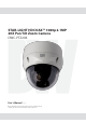
STAR-LIGHT HDCOAX™ 1080p 2.1MP 20X Pan Tilt Zoom Camera DWC-PTZ20X User’s Manual Ver. 03/20 Before installing and using the camera, please read this manual carefully. Be sure to keep it handy for future reference.
WARNING TO REDUCE THE RISK OF FIRE OR ELECTRIC SHOCK, DO NOT EXPOSE THIS PRODUCT TO RAIN OR MOISTURE. DO NOT INSERT ANY METALLIC OBJECTS THROUGH THE VENTILATION GRILLS OR OTHER OPENINGS ON THE EQUIPMENT. CAUTION CAUTION RISK OF ELECTRIC SHOCK DO NOT OPEN CAUTION: TO REDUCE THE RISK OF ELECTRIC SHOCK, DO NOT REMOVE COVER (OR BACK) NO USER-SERVICEABLE PARTS INSIDE. REFER SERVICING TO QUALIFIED SERVICE PERSONNEL.
FCC COMPLIANCE STATEMENT This device complies with Part 15 of the FCC Rules. Operation is subject to the following two conditions: (1) this device may not cause harmful interference, and (2) this device must accept any interference received, including interference that may cause undesired operation. FCC INFORMATION: This equipment has been tested and found to comply with the limits for a Class A digital device, pursuant to Part 15 of the FCC Rules.
IMPORTANT SAFETY INSTRUCTIONS 1. Read these instructions. 2. Keep these instructions. 3. Heed all warnings. 4. Follow all instructions. 5. Do not use this apparatus near water. 6. Clean only with dry cloth. 7. Do not block any ventilation openings. Install in accordance with the manufacturer’s instructions. 8. Do not install near any heat sources such as radiators, heat registers, stoves, or other apparatus (including amplifiers) that produce heat. 9.
Table of Contents Chapter 1 — Introduction .................................................................................................... 6 1.1 Features ................................................................................................................................. 6 Chapter 2 — Installation and Configuration ........................................................................ 7 2.1 Package Contents .................................................................................
Chapter 1 — Introduction 1.1 Features • Analog HD over Coax Technology with AHD/TVI Signal Support • 1/2.8" Image Sensor (1080p, 30fps) • 2.1MP, 1080p Resolution at 30fps • STAR-LIGHT™ Super Low Light Technology • 4.
Chapter 2 — Installation and Configuration 2.1 Package Contents Digital Watchdog’s 20x HD over Coax pan, tilt, zoom dome camera is designed with compact, small size, hard dome camera housing. The housing is constructed of aluminum, steel and plastic. The housing is designed to be mounted on a wall or a ceiling. The housing meets the Protection Classification IP66 standards for dust and moisture resistance.
2.2 Mounting the Camera The dome camera is for use in surface or pendent mounting applications, and the mounting surface must be capable of supporting loads of up to 10 lb (4.5 kg). (Wall mount and ceiling mount are sold separately.) The dome camera’s mounting bracket should be attached to a structural object, such as hard wood, wall stud or ceiling rafter that supports the weight of the dome camera. CAUTION: A silicone rubber sealant must be applied to seal the housing to secure waterproofing. 2.2.
CAUTION: Before installing the mounting bracket to the surface, pre-adjust the four mounting screws "A" on the base of the camera to best match the mounting bracket locked position. Unscrew the locking screw on the side of the dome's base and fit the tab of the mounting bracket into the locking slot. Screws "A" should not be too tight or too loose when the dome is in locked position. After setting the proper positions of screws "A", remove the mounting bracket and install it to the mounting surface.
2.3 Basic Configuration of Dome Camera System No.
NOTE: Open the DIP switch cover and change the setting of the DIP switch as needed. The cover should be closed after setting DIP switch. 2.4 Setting Dome Camera Address (ID To prevent damage, each dome camera must have a unique address (ID). The factory default ID is 1. Refer to ‘3.9 Dome Communication’ section for detailed information. 2.5 Setting Dome Camera Video Signal & Coaxitron Protocol S1 You can set the video signal with D1 in S1.
2.6 Connections • Connecting to the RS-485 The dome camera can be controlled remotely by an external device or control system using RS-485 halfduplex serial communications signals. • Connecting HD-TVI/HD-ANALOG Output connector Connect the HD-TVI/HD-ANALOG output (BNC) connector to the monitor or video input. • Connecting CVBS Output connector Connect the CVBS output (BNC) connector to the monitor or video input.
2.7 Getting Started Once the camera is properly installed, apply power to the dome camera. The dome camera will start a configuration sequence. FUNCTION TITLE 001 INFORMATION DISPLAY AF AE STATUS of FOCUS and AE EMPTY DATA ALARM DISPLAY ALARM:1 DOMEID:0001 360.0 090.
Chapter 3 — Program and Operation 3.1 Accessing the On-Screen Menu Utility You can call up the On-screen menu utility on your monitor by pressing the MENU key, the following Onscreen menu will appear: DOME MENU AUTO SCAN PRESET TOUR PATTERN PRIVACY ZONE CAMERA DOME COMMUNICATION ALARM DOME SETUP EXIT(ESC TO EXIT) 3.2 How to control the On-Screen Menu Utility Function Button MENU Call the On-screen menu utility. Up, Down Navigate through the menu items. Go into the sub-menu items.
3.3 Auto Scan The Auto Scan supports up to 17 programmed angles at different speeds. To setup an Auto Scan: AUTO SCAN SETUP NUMBER : 01 TITLE : A01 MODE : NORMAL SPEED : 5 STEP START ANGLE : ----- ----END ANGLE : ----- ----SCAN DIR : CCW SWAP : OFF DWELL : 03 SEC FOCUS : AUTO SAVE AND EXIT(ESC TO CANCEL) NUMBER TITLE MODE NORMAL VECTOR RANDOM SPEED SCAN DIR SWAP DWELL FOCUS 01 ~ 08, 10 ~ 17, 09: AUTO-PAN mode. up to 6 characters NORMAL, VECTOR, RANDOM (AUTO-PAN mode: NORMAL, RANDOM only).
5. Select “MODE” and “SPEED”. 6. Select “START ANGLE”. Press the IRIS Open key to go to the “CONTROL” settings. Move the desired position and the zoom position. Press the IRIS Close key then the “CONTROL” disappears. To adjust at the 0.1 degree interval, press the Tele or Wide key at the pan field and the tilt field. 7. Select “END ANGLE”. Press the IRIS Open key to go to the “CONTROL” settings. Move the desired position and the zoom position. Press the IRIS Close key then the “CONTROL” disappears.
3.4 Preset If you need to view specific places routinely, you should program Presets. A Preset is a programmed video scene with automatic pan, tilt, zoom, focus, and AE settings. Once programmed, placing the number position and pressing the PRST key will move the camera to the set scene and adjust the camera’s settings automatically. In addition, Presets may be assigned as a “home” position. Users can setup up to 240 individual presets. There are eight pages of Preset menu. Each page has 30 Presets.
Select “MOTION SETUP” and press the Left or Right key. Then the MOTION setup displays. MOTION SETUP SENSITIVITY: 10 POSITION : ALL DELAY : 00 SEC OUTPUT : OFF HOLD TIME : 03 SEC EXIT(ESC TO EXIT) Set SENSITIVITY Set POSITION Set DELAY Set OUTPUT Set HOLD TIME 00 ~ 20 ALL, CENTER 00 ~ 05 seconds OFF, OUT1, OUT2 03 ~ 99 seconds Select “AE SETUP” and press the Left or Right key. Then the AE setup displays. Refer to the AE SETUP in the camera setup. 6. Set “DWELL time”. (03 ~ 99 seconds) 7.
3.5 Tour There are 8 programmable Tours. Each Tour consists of up to 40 Preset positions, Patterns, Scans or other Tours (second-level). Using second-level Tours, it can be expanded to over 300 functions in a single Tour.
8. To edit the “TITLE”, follow the procedure of the Auto Scan above to edit titles. 9. Select “SAVE AND EXIT” and press the Right key. You can expand the Tour sequence by calling other programmed Tours. NOTE: The speed applies in the vector mode only. NOTE: In Tour mode, in conjunction with Preset and Auto Scan, you can make the camera travel from a Preset to another Preset at a specific speed.
3.6 Pattern The Pattern feature records the user’s control of the camera. Up to 8 Patterns can be stored and played back by pressing No. + PTRN keys subsequently. PATTERN SETUP (CTRL KEY) NO TITLE SEC PERCENT 1 : P01 000 00.0% 2 : P02 000 00.0% 3 : P03 000 00.0% 4 : P04 000 00.0% 5 : P05 000 00.0% 6 : P06 000 00.0% 7 : P07 000 00.0% 8 : P08 000 00.0% SAVE AND EXIT(ESC TO CANCEL) Follow steps below to program the Pattern: 1. Press MENU to display the main menu on the monitor.
3.7 Privacy Zone Hide up to 16 private scenes in a camera’s view. There are four pages of Privacy Zone menu. Each page has 4 Privacy Zones. PRIVACY ZONE SETUP NO METHOD COLOR 01 ON BLOCK BLACK 02 ON BLOCK BLACK 03 OFF ----- BLACK 04 OFF ----- BLACK NEXT PAGE SAVE AND EXIT(ESC TO CANCEL) (CTRL KEY) 1. Place the cursor at the field. 2. Press the IRIS Open key then the privacy area menu displays. Move the desired position. Press the IRIS Close key then the “CONTROL” disappears.
3.8 Camera Menu CAMERA SETUP FOCUS CONTROL WB CONTROL AE CONTROL CAMERA CONTROL SHARPNESS : 03 DIGITAL ZOOM : OFF IMAGE FLIP : OFF PRESET FREEZE : OFF RESOLUTION : 1080P/25 SAVE AND EXIT(ESC TO CANCEL) SHARPNESS DIGITAL ZOOM IMAGE FLIP PRESET FREEZE RESOLUTION The higher the value, the more edges in the picture will be enhanced. (0 ~ 10) OFF: Zoom range is limited to the optical. 2X: Zoom is extendable up to 2X of digital range. 4X: Zoom is extendable up to 4X of digital range.
• WB (White Balance) CONTROL WB SETUP MODE : AUTO R GAIN : --B GAIN : --SAVE AND EXIT(ESC TO CANCEL) MODE AUTO INCANDESCENT FLUORESCENT OUTDOOR MANAUL R GAIN B GAIN AUTO, MANUAL, INCANDESCENT, FLUORESCENT, OUTDOOR Computes the white balance value output using color information from the entire screen automatically. Auto white balance mode that is compatible with incandescent lamps. Auto white balance mode that is compatible with fluorescent lamps.
The NIGHT SHOT option removes the IR cutoff filter of the camera and makes the camera sensitive to near infrared. AUTO ON OFF Camera goes in to B&W mode at low light. B/W mode Color mode NOTE: AUTO in NIGHT SHOT function is not available when AE Control is set to “MANUAL”.
3.9 Dome Communication To prevent damage, each dome camera must have a unique address (ID). The factory default setting is 1.
3.10 Alarm ALARM SETUP NO PRI FUN IN OUT HLD LATCH 1 1 001 NO OUT1 03 OFF 2 1 --- OFF OFF 03 OFF 3 1 --- OFF OFF 03 OFF 4 1 --- OFF OFF 03 OFF DWELL : 03 SEC ALARM OUT SETUP SAVE AND EXIT(ESC TO CANCEL) NO (Number) PRI (Priority) FUN (Function) IN (Input) OUT (Output) HLD (Hold) LATCH DWELL (CTRL KEY) Alarm input number The lower number has higher priority (0 ~ 4) Stored function number to be called by alarm.
3.
• VIEW ANGLE SETUP VIEW ANGLE SETUP PANNING RANGE FLIP : 90° TILT ANGLE LIMIT : 07° SAVE AND EXIT(ESC TO CANCEL) FLIP OFF, AUTO, 90°, 100°, 110° and 120° OFF: The dome camera moves until 90° vertically. AUTO: When the camera reaches the floor directly above the moving object, it will stop. At that time, pull it down again to run the auto-flip function. When you use the panning range, it is recommended to use the flip mode to AUTO.
• ORIGIN OFFSET OFFSET SETUP (CTRL KEY) PAN OFFSET : 000.0 TILT OFFSET : 000.0 ENABLE : OFF SAVE AND EXIT(ESC TO CANCEL) This feature helps align a new dome camera exactly the same as a previously installed camera. Dome camera’s origin set and all data initialize option do not override offset values. Only the default set option in this menu will set the offset value to zero. This can be used to avoid ceiling obstructions. • FACTORY DEFAULT Select “FACTORY DEFAULT” to initialize the data.
• OSD DISPLAY OSD DISPLAY SETUP LANQUAGE : ENGLISH TITLE : DOMEID DOME OSD : ON FOCUS/EXPOSURE : OFF COLOR : YELLOW SAVE AND EXIT(ESC TO CANCEL) LANGUAGE Select the desired language. TITLE up to 6 characters DOME OSD ON, POSITION, ON (ZOOM), ZOOM, OFF All display or title will disappear when DOME OSD DISPLAY is set to OFF. FOCUS/EXPOSURE ON, OFF ON: FOCUS and EXPOSURE displays.
MOTOR SETUP Motor Setup menu provides the pan and tilt speed of a camera. User can set the desired speed with pressing the Left or Right key.
ORIGIN CHECK If you find the dome in the wrong position during operation, execute this origin check and the dome camera will return to the right position after the origin check operation. ORIGIN CHECK ARE YOU SURE? CANCEL OK • FUNCTION RUN Execute the function when you use a DVR without function keys (Preset. Pattern, Tour and Scan). FUNCTION RUN SETUP PRESET : --PATTERN : --TOUR : --SCAN : --HOME AUTO PAN ALARM OUT : ---EXIT(ESC TO EXIT) (CTRL KEY) 1.
• SYSTEM INFORMATION SYSTEM INFORMATION CAMERA TYPE : xxxx-Vx.xx H/W VERSION : Vx.xx-xxxx ROM VERSION : Vx.xxxxxx PROTOCOL : xxxx BAUDRATE : 9600(NONE) HD B/D VERSION : Vx.xx EXIT(ESC TO EXIT) The system information provides essential information about the dome camera if service is required. This screen displays the camera type and ROM version. The information on this screen cannot be modified.
Appendix A — Dimensions Units: Inch (mm) Figure – Dimension 35
Appendix B — Troubleshooting If problems occur, verify the installation of the camera with the instructions in this manual and with other operating equipment. Isolate the problem to the specific piece of equipment in the system and refer to the equipment manual for further information. Problem Possible Solution No video. Verify that power is connected to all pieces of equipment in the system. Verify that the power switches are in the ON position. Check the video connections. Poor video quality.
nw DIGITAL WATCHDOG@ Complete Surveillance Solutions Headquarters Office: 5436 W Crenshaw St, Tampa, FL 33634 Sales Office: 16220 Bloomfield Ave., Cerritos, California, USA 90703 PH: 866-446-35951 FAX: 813-888-9262 www.Digital-Watchdog.com technicalsupport@dwcc.