MEGApix® 2.1MP/1080p vandal ball IP camera DWC-MVA2Wi28T / DWC-MPVA2Wi28T User’s Manual Ver. 12/20 Before installing and using the camera, please read this manual carefully. Be sure to keep it handy for future reference.
Safety Information CAUTION RISK OF ELECTRIC SHOCK. DO NOT OPEN. CAUTION: TO REDUCE THE RISK OF ELECTRIC SHOCK, DO NOT REMOVE COVER (OR BACK) NO USER SERVICEABLE PARTS INSIDE. REFER SERVICING TO QUALIFIED SERVICE PERSONNEL. Warning Precaution This symbol indicates that dangerous voltage consisting of a risk of electric shock is present within this unit.
Important Safety Instructions 1. Read these instructions. - All safety and operating instructions should be read before installation or operation. 2. Keep these instructions. - The safety, operating and use instructions should be retained for future reference. 3. Heed all warnings. - All warnings on the product and in the operating instructions should be adhered to. 4. Follow all instructions. - All operating and use instructions should be followed. 5. Do not use this device near water.
Table of Contents Introduction Product and accessories..................................................................................................................................................................5 Parts identification.............................................................................................................................................................................6 Installation Disassemble the camera................................................................
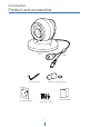
Introduction - Product and accessories Camera Cables Hex Allen wrench Mounting template Waterproof cap and gasket Screws and plastic anchors -2pcs 5 Quick setup guide
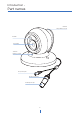
Introduction - Part names Camera tilt/rotation screw IR LED Fixed lens Camera panning screw DC power jack RJ-45 connector Waterproof cap 6
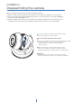
Installation - Disassembling the camera Before installing your camera, read the following cautions. 1. Make sure the mounting surface can hold up to five times the weight of your camera. 2. Do not let cables get caught in improper places or the electric line cover gets damaged. It may cause a breakdown or fire. 3. When installing your camera, do not allow any unauthorized personnel to approach the installation site. If you have any valuable things under the place, move them away.
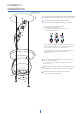
Installation - Installation Mounting template 12 1 Using the mounting template sheet or the camera itself, mark and drill the necessary holes in the wall or ceiling. 2 Connect the network cable and power cable respectively. See 'Installation - Cabling' for details. To use the camera’s waterproof wiring: a. Install the LAN cable into (a) . b. (b) will be assembled to (a) with a 1/4 turn. c. Thread (c) tightly to (b).
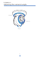
Installation - Adjusting the camera’s angle Panning 360° Rotation 360° Tilting 90° 9
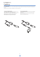
Installation - Cabling Two cabling options Use a PoE-enabled switch to connect data and power through a single cable and begin viewing and recording images instantly. A non-PoE switch will require an adaptor for power transmission. 1. Using a PoE-Enabled Switch The camera is PoE-compliant, allowing transmission of power and data via a single Ethernet cable. PoE eliminates the need for the different cables used to power, record, or control the camera.
Network setup - DW IP FinderTM Thumbnail view Firmware version Select network to scan Filter device type to scan Scan devices Show/hide thumbnail view Refresh thumbnail view Camera's uptime Open device configuration settings Bulk IP assignment Device's information Firmware upgrade 1 Go to: http://www.digital-watchdog.com and search for ‘IP Finder’ on the quick-search bar at the top of the page. 2 The latest IP Finder software will appear in the search results.
Web Viewer Screen - Basic Screen (Default) Password change is required at the initial connection in a factory reset state. 1 You cannot see the image, and the setup button is disabled. 2 Change the password with the CHANGE PASSWORD button. 3 After changing the password, login again by pressing the RE-LOGIN button. • Internet Explorer: After three failed attempts or the cancel button is clicked, you will experience a login fail.
Web Viewer Screen - Basic Screen 1 2 3 4 5 6 7 The web viewer is optimized with Internet Explorer 10 (or above) and Mozilla Firefox. “If VLC is not installed or the VLC plugin is not supported (Chrome), ‘Live Buffering’ and ‘Channel Select’ (Subjects 3 & 4 in the diagram) will display as ‘Live Viewer’. If so, select HTML5 (MJPEG) from the Live Viewer menu to view video. 1 Live video display. This is the region for the live video stream from the camera. 2 Setup a popup button.
Setup - Video & Audio Setup Video Configuration 1 2 1 Detail Page - When you select an item from the menu, you can set the details for the selected item. 2 Setup Menu Video & Audio [ VIDEO, OSD, ROI, SMART.
Setup - Video & Audio Setup Video Configuration 1 2 3 4 5 1 Live Video Channel Setup - The video can be configured to various settings with a combination of codec and resolution. The camera performance has to be considered when setting multiple channels. This effects on the performance of the camera. H.265 (HEVC) codec with higher bitrate may cause unstable live streaming or reload the webpage. 2 Codec - Choose the video codec.
Setup - Video & Audio Setup Video Configuration 6 7 8 GOP(Group of Pictures) Size - Set up the number of frames (P-frame) which contain only changed information based on the basic frame (I-frame). Regarding videos with lots of movement, if you set GOP size bigger, only the number of P-frames is bigger. As a result, the video resolution will be low but ‘File size’ and ‘Bit-rate can be decreased. GOP(Group of Pictures) Size I-frame and P-frame can be created for MPEG4, H.264 and H.
Setup - Video & Audio Setup Video Configuration 9 10 11 12 13 9 Target Bitrate - If Bitrate Control is set to be CBR, you can set the Target Bitrate. 10 Quality - For VBR control mode, The Target Quality of video can be setup. 11 Smart Core - Off / Smart.RC 12 Extension Option Off - You cannot use the Extension Option. SVC-T On - The H.264, H.
Setup - Video & Audio Setup OSD Configuration 1 2 3 1 Date / Time - Display the current time. 2 User Text - Output the TEXT entered by the user. Support a maximum of 30 characters. 3 Click ‘Apply’ to save all settings.
Setup - Video & Audio Setup Region of Interest Configuration 1 2 3 4 The region of interest function gives a more efficient picture quality for the indicated area to improve the qualities of movement in the scene without compromising the bandwidth. 1 Stream - Select the Stream. Currently supports only H.264, H.265 (HEVC). The function is not supported in the MJPEG codec. 2 Activation - Enable or disable the region of interest function. 3 Quality - Set the quality of the set area.
Setup - Video & Audio Setup Smart.RC Configuration 1 2 3 4 5 All menus are activated by selecting Smart.RC as the smart core menu on the Video Configuration page. 1 Stream - Select the Stream. Main Stream, Sub Stream are available. 2 Stream Quality - Select the Stream Quality. Low, Medium, High, and Extreme are available. 3 Dynamic GOP - This Dynamic GOP function keeps bitrate first. 4 FPS Drop - If enabled, the camera drops the FPS to maintain video quality.
Setup - Video & Audio Setup Privacy Mask Configuration 1 2 3 Use this function to mask areas that you want to hide on-screen to protect privacy. 1 Activation - Enable or disable the privacy mask function. 2 Area - Select the Area1 ~ Area16 and Set the privacy area. 3 Click ‘Save’ to save all settings. Click 'Cancel' to return to the previous setting. Click ‘Clear Area' to delete the selected Area1~Area16.
Setup - Camera Setup Camera Image Adjustment 1 2 3 4 5 6 1 Sharpness - The higher the number, the sharper the lines in the image will appear. 2 Brightness - The higher the number, the brighter the image will appear. 3 Contrast - The higher the number, the stronger the contrast between colors in the image will appear. 4 Saturation - The higher the number, the more saturated the colors in the image will appear. 5 Hue - The higher the number, the stronger the hue in the image will appear.
Setup - Camera Setup Camera Exposure Settings 1 2 3 4 5 6 7 1 Auto Exposure - Automatic exposure (AE) automatically sets the aperture or shutter speed, based on the external lighting conditions for the photo. 2 Exposure Level - The higher the number, the brighter the image will appear. 3 AE metering - AE metering mode refers to how a camera determines the exposure. 4 Shutter Speed - If this speed is faster, the moving object can be photographed without the ghost effect.
Setup - Camera Setup Camera Day & Night Settings 1 2 3 4 5 6 Day & Night - Auto: In this mode, the IR cut filter is removed automatically depending on the light condition around. - Day: In this mode, the IR cut filter is applied to the image sensor all the time. Thus, the sensitivity will be reduced in the dark light condition, but the better color reproduction performance is obtained. - Night: In this mode, the IR cut filter on the image sensor is removed all the time.
Setup - Camera Setup Camera Backlight Settings 1 2 This feature is used when lighting conditions may cause detail loss in the camera's view due to high contrast. 1 WDR (Wide Dynamic Range) - Enable or disable the WDR function. 2 Click ‘Save’ to save all settings. Click 'Cancel' to return to the previous setting. Click 'Default' to settings to the factory defaults.
Setup - Camera Setup Camera White Balance 1 2 3 4 1 Activation - Enable or disable the White Balance function 2 White Balance Mode - Select White Balance depending on the lighting conditions. 3 RGB Gain - The R/G/B gain can be set only when the White Balance Mode is set to Manual. 4 Click ‘Save’ to save all settings. Click 'Cancel' to return to the previous setting. Click 'Default' to settings to the factory defaults.
Setup - Camera Setup Camera Image Enhancement 1 2 3 4 1 3D Noise Reduction - 3DNR function suppresses digital noise and retains good video quality in low light conditions. 2 Mirror - Reverse the video from side to side. 3 Flip - Reverse the video from up to down. 4 Click ‘Save’ to save all settings. Click 'Cancel' to return to the previous setting. Click 'Default' to settings to the factory defaults.
Setup - Camera Setup Video Enhancement 1 2 1 Flicker - In case of flickering video, adjust the flickering values in this menu. 2 Click ‘Save’ to save all settings. Click 'Cancel' to return to the previous setting. Click 'Default' to settings to the factory defaults.
Setup - Network Setup Network Status This menu displays the camera's current network settings. To make any changes to the settings, you must go to the appropriate network settings tab.
Setup - Network Setup Network Settings 1 2 3 4 5 6 7 8 9 10 1 Network Type - Define the network IP address type. Select Static Mode for a fixed IP or Dynamic Mode for a dynamic IP address. If you select Static Mode, enter the camera's IP Address, Subnet Mask, Gateway, DNS Server, and all ports. If you select Dynamic Mode, the IP address will be assigned automatically by the DHCP network requirements.
Setup - Network Setup Auto IP Settings 1 2 3 1 General Setting - Enable or disable the Auto IP Settings. 2 Auto IP Settings Information - Display the camera's Unique ID and Auto IP address. 3 Click ‘Apply’ to save all settings.
Setup - Network Setup ONVIF Settings 1 2 3 Authentication None: Allow access to the camera without ONVIF authentication. WS - Usertoken: Allow access to the camera with WS-User Token of ONVIF authentication. WS - Usertoken + Digest: Allow access to the camera with WS-User Token and Digest of ONVIF authentication. 1 2 Discovery Mode - Enable or disable discovery mode. 3 Click ‘Apply’ to save all settings.
Setup - Network Setup UPNP Settings 1 2 3 1 General Setting - Enable or disable the UPNP function. 2 Friendly Name - Define the friendly name. Support a maximum of 30 characters and special characters (/ ~ ! $^ ( ) { } [ ] ; , ) cannot be used. ('@', '.', '_' ,'-', ' ') can be used. 3 Click ‘Apply’ to save all settings.
Setup - Network Setup DDNS Settings 1 2 3 1 DDNS Disable - If it is selected, DDNS service does not work. 2 Public DDNS - To use public DDNS service, select a site address listed on the list. After filling out the Host Name of the site the setup is completed by entering username and Password registered in that DDNS site. DDNS Provider Site Address DynDNS www.dyndns.com No-IP www.no-ip.
Setup - Network Setup FTP Settings 1 2 3 4 5 6 7 To transfer/save the image to the relevant sites through FTP, then FTP needs to be setup. 1 General Setting - Enable or disable the FTP function. 2 FTP Server Address - Define FTP Server IP Address. If the IP Address form is incorrect, a message box will be shown to try again. 3 FTP Upload Path - Define a path in FTP server to store video.
Setup - Network Setup SMTP Settings 1 2 3 4 5 6 7 8 9 10 11 To send/save the image to the relevant sites by Email, SMTP needs to be setup. 1 General Setting - Enable or disable the SMTP function. 2 Mode - Select the security mode of SMTP from Plain or SSL / TLS. After checking the account setup of your SMTP Server, you may select one. 3 SMTP Server Address - Define the SMTP Server Address. If the IP Address form is incorrect, a message box will be shown to try again.
Setup - Network Setup SNMP Settings 1 2 3 4 5 6 7 8 9 10 11 1 SNMPv1/SNMPv2 - Select the SNMPv1/SNMPv2 option and type the names of Read and Write communities. SNMP trap can be used to check periodically for operational thresholds or failures that are defined in the MIB. 2 SNMP Trap - Enable or disable the SNMP trap. SNMPv3 contains cryptographic security, a higher security level, which allows you to set the Authentication password and the Encryption password.
Setup - Network Setup RTSP Information 1 2 3 4 5 6 1 Target Stream - Select the stream you want to set. 2 Time out - Set the RTSP time out. The session is disconnected after the specified time out. 3 QoS Setting - Set the quality of service to ensure data transfer performance. 4 RTP Multicast - Check RTP Multicast Start/Stop. To activate RTP Multicast. 1. Click the “On” button. 2. Enter accessible RTP Multicast IP, the port for video stream control, RTP packet TTL. 3. Click the “Apply” button.
Setup - Trigger Action Setup Action Rules Configuration 1 2 1 Action rules List - It indicates the custom action rule information added to the Action rules list. 2 Click ‘Add’ to add custom action rules. Click ‘Modify' to modify selected items from the action rules list. Click 'Delete' to delete selected items from the action rules list.
Setup - Trigger Action Setup Action Rules Add / Modify 1 2 3 1 Name - Define the name of the action rules. Input text cannot exceed limit (3~15). 2 Action1 ~ Action5 - Select the action to take If the event occurs. 3 Click ‘Save’ to save all settings. Click 'Cancel' to return to the previous menu.
Setup - Trigger Action Setup Image Transfer Configuration 1 2 1 Pre / Post Alarm Image - Image Transfer due to event is configured by setting Image transfer rate and Pre / Post alarm duration. Descriptions 2 Number of Images Define the number of images transferred per second. Pre-alarm Duration Define the duration of the image transfer before an event. Post-alarm Duration Define the duration of the image transfer after an event. Click ‘Apply’ to save all settings.
Setup - Event Setup Event Rules Configuration 1 2 1 Event Rules List - It indicates the custom Event Rule information added to the Event Rules list. 2 Click ‘Add’ to add custom event rules. Click ‘Modify' to modify selected items from the event rules list. Click 'Delete' to delete selected items from the event rules list.
Setup - Event Setup Event Rules Configuration 1 2 3 4 1 Name - Define the Event rule name. Event - Select the event among motion detection, network disconnection, illegal login detected. Click 'Cancel' to return to the previous setting. You need at least one event set. 2 3 Rules - Select the action rule defined in the Trigger Action-Action rule menu. 4 Click ‘Save’ to save all settings. Click 'Cancel' to return to the previous setting.
Setup - Event Setup Motion Detection Configuration 1 2 3 4 5 1 Motion Detection - It shows the Motion event status. Event Alert Icon( ) appears if ‘Motion Detection’ is activated. 2 Area - Set the motion detected area. You can set up to four areas. 3 Activation - Enable or Disable motion detection function. 4 Sensitivity - Define the sensitivity of motion detection. If High value is selected, it will detect very small motion while it becomes relatively insensitive when Low value is selected.
Setup - Event Setup Temperature 1 2 3 4 1 Mode - Select Fahrenheit or Celsius. 2 Threshold - Define the temperature at which the event trigger occurs. 3 Temperature - It indicates the current temperature of the IP camera. 4 Click ‘Apply’ to save all settings.
Setup - Security Setup IP Address Filter Configuration 1 2 3 4 5 6 1 IP Address Filter - Enable or disable the IP filter function. 2 IP Filter Type - Select the recording IP filter type. 3 Click ‘Apply’ to save the settings. 4 Filter IP Address - Display the filtered IP address. 5 IP Address - Define the IP address you want to apply the IP filter. 6 Click ‘Add’ to add the IP address to the list. Click ‘Remove’ to remove the IP address selected in the list.
Setup - Security Setup RTSP Authentication Configuration 1 2 1 RTSP Authentication - Enable or disable the RTSP authentication. 2 Click ‘Apply’ to save all settings.
Setup - Security Setup IEEE 802.1X Configuration 1 2 3 4 5 6 7 8 9 The feature is needed when connecting the camera to the network protected by the IEEE 802.1X. 1 IEEE 802.1x - Enable or disable the IEEE 802.1x feature. 2 Protocol - MD5: It provides one-way password-based network authentication of the client. - PEAP: It is similar to TTLS in that it does not require a certificate on the client-side. - TTLS/MD5: It does not require a certificate on the client-side.
Setup - Security Setup HTTPS Configuration 1 2 3 HTTPS encrypts session data over SSL or TLS protocols instead of using plain text in socket communications. 1 Certificate - Select an installed certificate. If you cannot select a certificate, please install the certificate from the Security->Certificates menu. 2 HTTPS connection Policy - Select one of “HTTP”, “HTTPS”, “HTTP and HTTPS” depending on the connected web, ONVIF, RTSP over HTTP.
Setup - Security Setup Certificates Configuration 1 3 2 4 5 6 7 9 10 8 1 Server/Client Certificates - Shows the installed certificates. 2 Create Self-Signed Certificate - A self-signed SSL certificate is an identity certificate signed by its creator. But they are considered to be less trustworthy. 3 Properties - Shows information about the selected certificate. 4 Delete - Delete the selected certificate.
Setup - Security Setup Certificates Configuration 1 3 2 4 5 6 7 8 9 10 Detail for Install Certification. 1 Certificate From Signing Request - Select to install a signed certificate returned from the CA. 2 Certificate And Private Key - Select to install Certificate And Private Key to install a certificate and private key. 3 Certificate Name - Enter a unique name to identify a certificate. 4 Select File - Choose the certification file. 5 OK - Request installing a certificate.
Setup - Security Setup Service Configuration 1 2 1 SSH - Enable or disable the SSH function. 2 Click ‘Apply’ to save all settings.
Setup - System Setup System Information 1 2 3 System Capability information. 1 Device Name - You can define the device name. 2 Location - Shows the camera's location. 3 Click ‘Apply’ to save all settings.
Setup - System Setup System Diagnostics 1 Shows basic hardware functions after inspection. 1 Shows Uptime, SD card, NAND, EEPROM, Audio chip, Important file system, and NTP Status. Warning: If the camera is abnormally terminated, a download button will appear on the diagnostics page to download a file that allows you to check the error information you can.
Setup - System Setup Firmware Update 1 2 3 1 Version Information - It shows the current Firmware Version in the system. 2 Web Update - Select the Firmware file in your computer by clicking [Select file] button. 3 Start F / W Update - Click this button to start the update. Progress of uploading will be displayed using Progress Bar. If you assign the wrong file name, an error message will be shown. Warning: 1. Do not turn off the power of the camera during the Firmware update.
Setup - System Setup Firmware Update 4 5 6 7 8 9 4 FTP Server Address - Define FTP Server IP Address. If the IP Address form is incorrect, a message box will be shown to try again. 5 FTP Port - Define the FTP Server Port. If Port is not appropriate, it is impossible to access to FTP Server. 6 User ID - Define User ID to access to the FTP Server. Fill out the correct User ID registered in the FTP Server. 7 Password - Define Password to access to the FTP Server.
Setup - System Setup Date & Time Settings 1 2 3 4 5 6 7 1 TimeZone Setup - Choose the time zone for the camera. It will be activated after clicking the ‘Apply’ button. Before setting below ‘New Camera Date and Time’, set correct Timezone first. 2 Time Format - Select the time format yy-mm-dd or mm/dd/yy. 3 Current Date and Time - Shows the current date and time setting in the Camera. 4 Synchronize with my computer - Set the date/time using those of PC currently connected.
Setup - System Setup DST Settings 1 2 3 Daylight Saving Time (DST) is the practice of setting the clocks forward one hour from standard time during the summer months, and back again in the fall, to make better use of natural daylight. 1 General Setting - Enable or disable the DST function. 2 Date and Time Settings - Set the start time and end time that the DST applies. 3 Click ‘Apply’ to save all settings.
Setup - System Setup Users Management 1 2 3 1 Users - List all the user accounts for authentication. 2 Add - Register a new user. ID Password Retype Password Password Hint User Authority 4 Enter a new user ID. Admin already exists. Enter the user password. (Check the password) Enter the user password again for verification. Enter the password hint. Select Operator or Viewer. Viewer: Only monitoring is allowed. Operator: Most of the functions are allowed except ‘Setup’.
Setup - System Setup System Log 1 2 3 1 Filter - Select a date, time, sort, or type of log to filter the log. 2 Click the 'Refresh' button to refresh the log list. Click 'Filter' to view the filtered log. Click 'Backup' to backup the filtered log. 3 System Log List - The filtered log is displayed.
Setup - System Setup Factory Reset 1 2 1 Reset to the factory defaults - Return the setup to the factory default. All - Reset all Settings to the factory defaults. Except for Network Settings and User Settings - Except Network, User related settings, reset all others to the factory default. 2 Click ‘Apply’ to save all settings.
Setup - System Setup Restart If you click the ‘RESTART’ menu, a message box will be shown to confirm. Click the ‘OK’ button to restart.
Setup - System Setup System Open Source License This menu will show you all the list of System Open Source License in the camera. Open Source Name / Version / License.
Network Setup - Quick Start of Network Connection Please follow the steps below to complete the initial setup of the network function. 11 Access your IP Camera via the Internet: If you use a static IP address assigned by your ISP i Please do not power on the IP Camera until instructed. 1) Open Internet Explorer. i Temporarily disable any proxy servers configured in 2) Type the IP of the IP Camera. 3) If you use a router, type the routers’ static IP and the internet Explorer.
Network Setup - DDNS Registration If you have a DYNAMIC IP service from your Internet Service Provider (ISP), you can’t tell the current IP address of the IP Camera. To solve this problem, you have to register with our DDNS service. At first, you have to check if you are using dynamic addressing. If so, register your IP Video Server on our DDNS website before you configure, setup, or install the IP Camera. Even though your IP is not dynamic, you will get benefit if you register to DDNS.
Network Setup - Guide to the Network Environment Please configure the IP Camera at the installation site. You must determine your network scenario to configure the IP Camera with the proper TCP/IP settings. This tutorial will guide you through the process. Before actually configuring the IP Camera, determine settings to be applied. Record those settings to be used to configure your IP Camera for reference. 4 If prompted for ID and Password, use ‘admin’ for both entries. The default web port number is 80.
Network Setup - Setup Case A, B Case A: Dynamic IP + Personal Router [Most SOHO] Configure your IP Camera’s TCP/IP properties as follows: 1 Network Type: STATIC (even though you have Dynamic IP from your ISP, use STATIC on the IP Camera) 2 Internet Address: A private IP address such as Camera 192.168.0.200 (Example) i You need to assign an IP address to the IP Camera just PC as you do with PC.
Network Setup - Setup Case C, D Case C: Static(Fixed) IP [Dedicated line directly to the IP Camera] Case D: Dynamic IP + DSL/Cable Modem [Connected directly to the IP Camera] Camera Camera Cable/xDSL Modem (ISP Provided) Gateway or Router at ISP Phone Line or CATV Public Line Internet Internet i To connect the IP Camera directly to a modem, Configure your IP Camera’s TCP/IP properties as follows: 1 Network Type: STATIC power down and reset the modem.
Network Setup - Port Forwarding After entering the correct TCP/IP settings, you are ready for ‘Port Forwarding’ (Cases A, B). 1 Please record the TCP/IP settings of your IP Camera for future reference. You may need this information to access your IP Camera and to configure ‘Port Forwarding’. IP Camera TCP/IP Settings IP Address Subnet Mask Default Gateway Preferred DNS Server DDNS Server Web Port 2 After clicking ‘Apply’, the system will prompt for a reboot.
Network Setup - Starting IP Camera After forwarding correctly the Web Port, through your router (if applicable), install the IP Camera in a proper location. 1 Locate the serial number located on the label attached to the bottom of the IP Camera, you will need this for DDNS registration. 2 Connect the IP Camera to your router or cable/DSL modem (per your network scenario) via a Cat5/5e UTP Ethernet network cable. 3 Supply power to the IP Camera.
Appendix FAQ 8. How do I “PING” an IP address? 1. My POWER light is not on? 1) Open an MS-DOS (or Command) prompt Power is not being supplied to the unit. Please use the 2) At the prompt type - “ping xxx.xxx.xxx.xxx” (without the power supply shipped with the unit and verify that a quotes and replace the “x” s with an IP address) power source is active from the attached power outlet 3) Press Enter used to connect the adapter.
Specifications - Dimension Unit: inches (mm) 3.74” (95mm) 14.92” (25mm) 4.
Specification SECURITY AND NETWORK CAMERA Network protocol IPv4: TCP/IP / UDP / AutoIP / RTP(UDP/TCP) / RTSP / NTP / HTTP / HTTPS / SSL / DNS / DDNS / DHCP / FTP / SMTP / ICMP / SNMPv1/v2/v3(MIB-2) / ONVIF Security HTTPS (SSL), IP filtering, 802.1x, Digest Authentication Plug-in CGI, API, ONVIF Image sensor 1/2.8” 2.1MP/1080p CMOS Total pixels 1945 (H) X 1109 (V) Focal length 2.8mm, F2.
Warranty Information Digital Watchdog (referred to as “the Warrantor”) warrants the Camera against defects in materials or workmanship as follows: Labor: For the initial five (5) years from the date of the original purchase if the camera is determined to be defective, the Warrantor will repair or replace the unit with the new or refurbished product at its option, at no charge. Parts: Also, the Warrantor will supply replacement parts for the initial two (2) years.
Limits and Exclusions There are no express warranties except as listed above. The Warrantor will not be liable for incidental or consequential damages (including without limitation, damage to recording media) resulting from the use of these products, or arising out of any breach of the warranty. All express and implied warranties, including the warranties of merchantability and fitness for a particular purpose, are limited to the applicable warranty period set forth above.
DW® East Coast office and warehouse: 5436 W Crenshaw St, Tampa, FL USA 33634 DW® West Coast office and warehouse: 16220 Bloomfield Ave, Cerritos, CA USA 90703 PH: 866-446-3595 | FAX: 813-888-9262 www.Digital-Watchdog.com technicalsupport@dwcc.tv Technical Support PH: USA & Canada 1+ 866-446-3595 International 1+ 813-888-9555 French Canadian: 1+ 514-360-1309 Technical Support hours: Monday-Friday 9 a.m. to 8 p.m.