
Camera Accessories Compatibility Chart
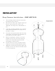
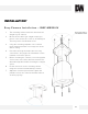

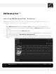
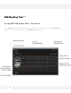
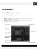


Table Of Contents
- Slide Number 1
- Slide Number 2
- Slide Number 3
- Slide Number 4
- PARTS & DESCRIPTIONS*
- PARTS & DESCRIPTIONS*
- DIMENSIONS*
- DIMENSIONS*
- Slide Number 9
- NETWORK CONNECTION*
- INSTALLATION*
- INSTALLATION*
- INSTALLATION*
- Slide Number 14
- Slide Number 15
- Slide Number 16
- Slide Number 17
- Slide Number 18
- Slide Number 19
- Slide Number 20
- Slide Number 21
- WEBVIEWER*
- WEBVIEWER*
- WEBVIEWER*
- WEBVIEWER*
- WEBVIEWER*
- WEBVIEWER*
- WEBVIEWER*
- WEBVIEWER*
- WEBVIEWER*
- WEBVIEWER*
- WEBVIEWER*
- WEBVIEWER*
- WEBVIEWER*
- WEBVIEWER*
- WEBVIEWER*
- WEBVIEWER*
- WEBVIEWER*
- WEBVIEWER*
- Slide Number 40
- Slide Number 41
- Slide Number 42
- Slide Number 43
- Slide Number 44
- Slide Number 45
- Slide Number 46
- Slide Number 47
- Slide Number 48

1. The mounting surface must bear five times
the weight of your camera.
2. Do not let the cables get caught in improper
places or the electric line cover to be
damaged. This may cause a breakdown or
fire.
3. Using the mounting template or the camera
itself, mark and drill the necessary holes in
the wall or ceiling.
4. Pass wires through and make all necessary
connections. See page 8 for information on
the network connection options.
5. Before mounting the camera, loosen the
pan/tilt screw on the side of the camera's
bracket. This will make adjustment after
mounting the camera easier.
6. Fix the camera on to the mounting surface
using the screws included with the camera.
7. Adjust the camera's pan and tilt. Tighten the
pan/tilt screw on the camera's bracket until it
is secured properly.
INSTALLATION*
11
Easy Camera Installation – DWC- MB72I4V