DWC-MB950TIR IP 5MP Weather Proof Bullet Camera Before installing or operating the camera, please read and follow this manual carefully.
PRECAUTIONS Do not open or modify. Do not open the case except during maintenance and installation, for it may be dangerous and can cause damages. Do not put objects into the unit. Keep metal objects and flammable substances from entering the camera. It can cause fire, short-circuits, or other damages. Be careful when handling the unit. To prevent damages, do not drop the camera or subject it to shock or vibration. Do not install near electric or magnetic fields.
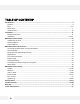
TABLE OF CONTENTS* Introduction.......................................................................................................................................................4 Features........................................................................................................................................................4 Parts .........................................................................................................................................................
FEATURES* ONVIF Compliant Profile S 5 Megapixels (2592x1920, 10fps) Resolution Triple Codecs (H.264, MJPEG, MPEG4) with Dual-Stream 1/2.5” 5MP CMOS Sensor (20% Larger Than 1/3” CMOS Sensor) 3.
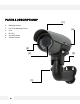
PARTS & DESCRIPTIONS* [5] 1. Mounting Bracket 2. Pan & Tilt Adjusting screws 3. Lens 4. IR LEDs 5. Sunshield Cover 6.
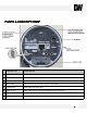
PARTS & DESCRIPTIONS* Camera Part Description 1 RS485 +/- RS485 connections for remote camera control 2 Sensor Inputs +/- Connect up to 2 sensor inputs to the camera 3 Alarm Output +/- Connect 1 Alarm output control from the camera 4 SD Card Slot Micro SD card slot for local storage (not included) 5 Network Port RJ45 Cable Connection Port 6 Audio In/ Out Built-in Microphone and Audio Amplifier output connector 7 Power Ports DC Power port and AC + DC Cable power connectors available 8 Reset
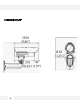
DIMENSIONS* 7
INSIDE THE BOX – MB950TIR* The following items are included with the MEGAPIX camera.
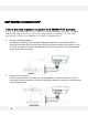
NETWORK CONNECTION* There are two options to power the MB950TIR camera. Use a PoE-enabled switch to connect data and power through a single cable and begin viewing and recording images instantly. A non -PoE switch will require an adaptor for power transmission. 1. Using a PoE-Enabled Switch The MEGApix Camera is PoE-Compliant, allowing transmission of power and data via a single Ethernet cable. PoE eliminates the need for the different cables used to power, record, or control the camera.
INSTALLATION* 1. Use the camera’s mounting template to mark and drill the mounting holes. 3. Mount the camera’s arm support onto the mounting plate. 4. To connect all appropriate cables to the camera and complete the installation, unscrew the back cover of the camera. 2. Fix the mounting plate to the surface using the three (3) provided screws, washers, and wall anchors.
INSTALLATION* 5. Remove the spindle fork connecting the camera module to the mounting bracket by pushing in the spindle. 6. Screw the spindle fork on to the camera. 7. Set the camera onto the arm by pushing the spindle and placing the fork on the spindle.
INSTALLATION* 8. Tighten the screws on the other side of the spindle to lock the camera on to the mounting bracket. 9. To adjust the camera’s pan and tilt, loosen the pan & tilt screw locks and adjust them accordingly. 10. To adjust the camera’s lens, focus, and zoom, unscrew the front cover by rotating it counter clock-wise. 11. Use the two handles at the base of the lens to adjust the focus and the zoom.
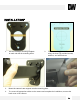
INSTALLATION* 12. You may also use the 2nd Video output located near the camera’s lens for easy adjustment during installation. 13. After adjusting the lens, remove a drying agent pack from one of the silver packages stored inside the accessories package*. 14. Remove the sticker from the drying agent pack and insert it in the front under the lens as shown in the image*. 15. Screw the front cover back on to the camera. 16. If using wide angle, shift the camera’s hood back to avoid blocking the view.
IP FINDER SOFTWARE* Installing IP Scan Software IP Finder searches for all the available Digital Watchdog devices currently connected to your network. 1. Install IP Scan to find the MB950TIR Cameras on the local network. The IP Scan software can be found on the included CD. Run IP Scan and install it onto your PC. 2. When setup is complete, launch the IP Scan software. 3. To find your MB950TIR cameras, click the Scan button. 4.
IP FINDER SOFTWARE* DHCP The Dynamic Host Configuration Protocol (DHCP) is a network configuration protocol that allows a device to configure automatically according to the network it is connected to. If your network supports DHCP and your MEGAPIX camera is set to DHCP, IP Finder will automatically find and set your MEGAPIX camera to correspond with your network requirements.
CAMERA REBOOT* Resetting the Camera Pressing the reset button on the camera’s control board for six (5) seconds will initialize all environmental variables to factory default. Previous setup for IP default, time, etc. will be deleted. If a system’s IP address is lost, reset the camera back to factory default. The following are the default network settings. IP Mode DHCP IP Address 192.168.1.2 Subnet Mask 255.255.255.0 Gateway 192.168.1.
WEBVIEWER* Remote Video Monitoring Via Internet Explorer Monitor and configure the MEGAPIX camera through a built -in web viewer. When accessing an IP camera using the web interface for the first time (or when the IP address changes), some configuration for ActiveX controls are required. 1. Open an IE browser 2. Type in the IP address in the URL: http:// (e.g. http://10.1.21.53). 3. Default Username and Password: root/ pass. 4.
WEBVIEWER* GUI Description 18
WEBVIEWER* Relay Input & Alarm Output Control The MB950TIR supports 2 Sensor Inputs and 1 Alarm Control Output. Use the camera’s Control bar and status indicators to manage the camera’s relay and alarm inputs and outputs. The View Size controls adjust the viewable screen size in Live View. The Zoom feature can be used once one of the zoom view modes is selected. See page 20 for more information. Record and Snapshot will capture video/snapshots to the local hard drive.
WEBVIEWER* Digital Zoom The Digital Zoom feature allows zooming in on a specific area. To control the Camera’s Digital Zoom: 1. When using the View Size controls, a magnifying glass icon will replace the mouse pointer icon. 2. To magnify a specific area, place the magnifying glass icon over the desired area and left click the mouse. Additional left mouse clicks will continue to magnify wherever the mouse is placed. 3. To zoom out, right click the mouse. 4.
WEBVIEWER* First Stream & Second Stream The MB950TIR supports multiple simultaneous streams (4 profiles) The Streams can be switched from the camera’s web viewer by selecting the corresponding stream from the drop down menu in the Steam Control option. The stream’s current resolution and framerate information will be displayed in the information section. To setup the different streams: a. Go to ‘Setup’ at the top right-hand corner of the screen. The setup menu will appear. b.
WEBVIEWER* Export Image Export a screenshot of the current live video to your computer. 1. 2. Make sure the directory path has been setup. To do so: 1. Go to Client Settings at the top right-hand corner of the screen. 2. Press ‘Select Path’ to select the directory where all exported images will be saved to. Settings will be saved automatically. 3. Click on the ‘Live View’ link at the top right-hand corner of the screen to return to the camera’s live display.
WEBVIEWER* Instant Recording Record live video to your local drive. To Setup Instant Recording Make sure the directory path is setup. To do so go to Client Settings at the top right-hand corner of the screen and press ‘Select Path’ To Start and Stop Instant Recording To Start, press the icon on the control menu bar. A window will appear to notify you instant recording has begun. The button will blink red indicating you are currently recording video. To Stop, press the 23 button again.
WEBVIEWER* Controlling the Camera using the Virtual Joystick Use the different buttons in the Pan/ Tilt Controller to adjust the camera’s position, zoom and focus, and control the camera’s PTZ functions. To control the Camera’s Pan, Tilt, and Zoom 1. PTZ Directional Buttons-When the camera is in zoom, use the directional arrows to control the zoom screen’s movement and focus on a specific area of the camera’s field of view.
WEBVIEWER* Client Setup It is recommended that you setup your camera’s client settings the first time you access the camera to prevent any feature malfunction in the future. The Client Setup provides options to modify the recording path, streaming protocol and buffering time. Streaming protocol and buffering time relate to streaming settings for the web UI on the client PC. These settings are only applied for the browser session, and don’t persist after the browser is closed.
WEBVIEWER* Setup > System> Information The Setup interface is primarily used for viewing and configuring the IP camera’s settings. To access the Setup page, click the Setup link at the top right-hand corner of the camera’s live display.
WEBVIEWER* Setup > System> Generic Settings Use the Generic Settings Page to modify the camera’s Name, Date & Time format, Sensor Input Type, LED Management, HTTP Port Setup and Language Selection. Camera Name- Enter a camera name if a specific name is desired System Time-3 options are available: Manual: insert time manually PC Time: set to the current PC time Network Time Server: periodically synchronizes with a time server For Network Time Server two standard options are provided.
WEBVIEWER* Setup > System> Generic Settings Use the Generic Settings Page to modify the camera’s Name, Date & Time format, Sensor Input Type, LED Management, HTTP Port Setup and Language Selection. LED- The camera LED lights can be enabled or disabled. The bullet model has an additional setting which controls operation of an external IR LED source. The External IR Output Level controls the circuit voltage which is used to turn on/off the external IR LED.
WEBVIEWER* Setup > System> User Account Management User accounts can be added, edited or deleted via the controls in the left corner. Users are assigned to a group (admin, operator or viewer). To edit or delete an account, highlight the account in the User List window and click the edit/delete button. After making changes, click SAVE to apply changes.
WEBVIEWER* Setup > System> Maintenance Use the Maintenance setup page to upgrade the firmware, Import or Export Settings, Reset the camera to factory default, or reboot the camera. Firmware Upgrade- The firmware can be upgraded using the web UI or an SD card. After upgrading, the ActiveX controls and browser cache should be cleaned to prevent old controls & pages from being used. IP and User Account settings can be preserved by checking the appropriate boxes.
WEBVIEWER* Setup > System> Maintenance Use the Maintenance setup page to upgrade the firmware, Import or Export Settings, Reset the camera to factory default, or reboot the camera. Firmware Upgrade Using the SD Card- The SD card should be empty of any existing files before proceeding. 1. Rename the firmware file to ev-fw.bin, and copy the file to the SD card. 2. Insert the card into the camera’s SD card slot. 3. Power on the camera, and wait about 1 minute. 4.
WEBVIEWER* Setup > System> Maintenance Use the Maintenance setup page to upgrade the firmware, Import or Export Settings, Reset the camera to factory default, or reboot the camera. Clean the ActiveX and IE Cache & History- After upgrading, the ActiveX controls and IE cache & history should be cleared to prevent old pages and controls from being used. 1. Close all instances of IE and open 1 IE window. 2. In the right corner, select Tools->Manage Add-ons 3.
WEBVIEWER* Setup > System> Maintenance Use the Maintenance setup page to upgrade the firmware, Import or Export Settings, Reset the camera to factory default, or reboot the camera. Import/ Export Camera Configuration- Export will save the camera’s configuration settings to the PC in an archive file. To import, first use Browse to select a camera’s exported configuration file. Next click Import to proceed with replacing the current camera settings with the settings in the configuration file.
WEBVIEWER* Setup > System> Local Storage The MB950TIR supports local recording to a micro SD Card. Use the Local Storage setup page to format and setup the card properly. Format: Format will format the card. Note: contents of the SD card will be lost. Double click on folders to go up/down a directory level.
WEBVIEWER* Setup > System > Recording/ Snapshot There are 2 methods of recording: Event -Triggered and Continuous Recording. Both can be used simultaneously. Cyclic Recording offers options for whether to overwrite old recordings when space on the storage reaches capacity. Event Triggered Recording- When recording is done via event triggers, Record Setting will define how the recording is performed. Stream Source will only display currently enabled video profile streams.
WEBVIEWER* Setup > System > Recording/ Snapshot There are 2 methods of recording: Event -Triggered and Continuous Recording. Both can be used simultaneously. Cyclic Recording offers options for whether to overwrite old recordings when space on the storage reaches capacity. Snapshot Settings- Snapshot recording will record a group of snapshots. The maximum value for Pre-alarm and Post-alarm time is 5 seconds.
WEBVIEWER* Setup > Network> IP Settings Use the IP Settings page to set the camera to DHCP or Static IP. If Static is selected, manually enter the camera’s IP address, subnet mask, Gateway and primary and secondary DNS information. In the IP Setting tab, select DHCP or Static IP for the camera. If using static, then enter the appropriate settings for your environment. Please confirm all network related settings with the network administrator prior to making any changes. a.
WEBVIEWER* Setup > Network> WLAN Settings Only wireless dongles from the manufacturer are supported. In the WLAN setting tab, click the Enable Wi -Fi option to enable WiFi. Any WiFi changes will only be applied after clicking the Save button in the IP Setting tab. Auto Scan can be used to scan available networks. An available network can be selected by clicking the option and entering a password if required. Manual can be used to directly configure WiFi settings.
WEBVIEWER* Setup > Network > Streaming The camera can stream using UDP, TCP or HTTP. The client application connecting to a camera can direct which protocol to use. The method of streaming will likely determine the need and extent of any router configuration that may be required. The port settings all relate to camera ports. If streaming outside of a LAN (e.g. to the internet), then routers on both the camera and client side need to provide necessary access for these ports.
WEBVIEWER* Setup > Network > Streaming The camera can stream using UDP, TCP or HTTP. The client application connecting to a camera can direct which protocol to use. The method of streaming will likely determine the need and extent of any router configuration that may be required. Video and audio server ports only need be changed if a network has security or operational restrictions using these ports. In most cases, the RTP/RTCP video and audio should use the default values.
WEBVIEWER* Setup > Network > DDNS DDNS is used to map a dynamically assigned IP address (a device using DHCP) with a hostname. If the IP camera uses DHCP, a DDNS service can provide a hostname for use with the IP camera. Registration with a DDNS service provider (ddns.nu, dyndns.org) is required for use of this feature. 1. To use DDNS, select the Use DDNS checkbox. 2. Select one of the DDNS System Names from the drop down list. 3. Enter Username & Password.
WEBVIEWER* Setup > Network > Access Filtering Access filtering can be used to allow or deny access by IP addresses. Set the Filter Type to either Allow All or Deny All. Exceptions can be added to the chosen filter type. IP addresses can be entered as a single IP, by network or a range of IP addresses. The network option uses the CIDR subnet mask format.
WEBVIEWER* Setup > Video / Audio > Video Settings Use the Video Settings page to select the number of profiles the camera will stream simultaneously and setup each of the profiles. Power Frequency- Use this setting to adjust the camera’s display has flickering issues. This may occur due to artificial lighting and can be adjusted by modifying the Power Frequency. Select from 50GHz or 60GHz. Max Resolution- Select the camera’s resolution. By default, the camera is setup to 1080p (2.1 Megapixels).
WEBVIEWER* Setup > Video / Audio > Video Settings Use the Video Settings page to select the number of profiles the camera will stream simultaneously and setup each of the profiles. Profile Setting- The Video Profile Settings control the ROI (Region of Interest) characteristics. The ROI video is streamed via RTSP protocol. See the “Streaming ROI” section for more on viewing ROI video. The number of available ROI profiles for viewing can be set by selecting the appropriate option button.
WEBVIEWER* Setup > Video / Audio > Audio Settings Select the desired audio codec. The Bitrate is configurable for some codecs. Encoder Type-Select from the available options: NONE, AAC, G.711 u-law (default), G.711 a-law , G.726. Bitrate- If AAC or G.726 are selected as encoder type, setup the bitrate. Select form 16, 32, or 40 Kbps. Line-in Gain- Adjust the volume of input audio from 0 to 10. Default value is 6. Line-Out Gain- Adjust the volume of output audio from 0 to 10.
WEBVIEWER* Setup > Video / Audio > Color Settings Use the Color Settings to adjust the Day/ Night Settings as well as image color control settings. Day/Night Settings: IR Cut Filter The Auto Mode (AE) allows adjusting the light sensor’s sensitivity to day/night conditions to fine tune the IR cut filter operation when the Auto Mode (Light Sensor) isn’t optimal for a specific environment. In Transfer Threshold are 2 settings: From Day to Night and Back to Day.
WEBVIEWER* Setup > Video / Audio > Color Settings Select the desired audio codec. The Bitrate is configurable for some codecs. Color & Sensor Settings: Image settings for both day and night are available via the Day & Night Time Profile tabs. The relevant settings will be applied to the camera based on the camera’s present mode of operation (e.g. day or night). In the Color Settings Tab, adjust the following options: Brightness: select values from 0~255. Default value is 128.
WEBVIEWER* Setup > Video / Audio > Color Settings Select the desired audio codec. The Bitrate is configurable for some codecs. Color & Sensor Settings: Image settings for both day and night are available via the Day & Night Time Profile tabs. The relevant settings will be applied to the camera based on the camera’s present mode of operation (e.g. day or night).
WEBVIEWER* Setup > Video / Audio > Text Overlay The video display format can be changed by selecting one of the available timestamp formats and enabling display of the camera name . Select from the following available text display options: yyyy-mm-dd hr:min:sec mm-dd-yyyy hr:min:sec mmmm-dd-yyyy hr:min:sec Choose to enable or disable attaching the camera’s name to the text overlay.
WEBVIEWER* Setup > Video / Audio > Privacy Masking Privacy mask can be used to block out areas from view and triggering motion detection. Up to 5 privacy masks can be applied; each mask can be 80 x 45 in size. 1. 2. 3. 4. 5. Check the box next to the Privacy Masking you want to edit. Check the Draw button next to the Mask’s name. Select the color of the mask you want to setup (black by default). Using your mouse, draw the mask on the camera’s display window.
WEBVIEWER* Setup > Event Handle> Event Rule The Event Rule page is used to define actions (e.g. record to SD card) in response to the triggering of an event (e.g. motion detection ). Rule Name is a user defined name for a user defined trigger/action. Trigger Type- select what action will trigger the set command. Select form the available options: Motion Detection – Set action will be activated when the camera detects motion. If selected, check which motion areas will apply to this rule.
WEBVIEWER* Setup > Event Handle> Event Rule The Event Rule page is used to define actions (e.g. record to SD card) in response to the triggering of an event (e.g. motion detection ). Action determines what action you would like the camera to perform once the selected trigger has been detected. Select from the following options: Digital Output – The camera will activate the digital output when the trigger set is detected.
WEBVIEWER* Setup > Event Handle> Event Server The Event Server page has configuration options for event notification & action using email, network storage, FTP, TCP and HTTP. E-Mail Settings – Use this setup page to enter the information for an SMTP server for the e-mail notifications feature. Enter the SMTP server for Server Address and all additional relevant details. The username may only contain alphanumeric characters and the underscore character, “_”.
WEBVIEWER* Setup > Event Handle> Event Server The Event Server page has configuration options for event notification & action using email, network storage, FTP, TCP and HTTP. Network Storage– Use this setup page to enter set up a Network Storage device. Server Type- Select whether the network storage you want to setup is NFS or Samba. Server Address- enter the server’s URL or IP address.
WEBVIEWER* Setup > Event Handle> Event Server The Event Server page has configuration options for event notification & action using email, network storage, FTP, TCP and HTTP. TCP/ HTTP Recipient– Use this to setup the recipients for TCP and HTTP Notifications from the camera. The TCP and HTTP Recipient allows event notifications to be sent from the camera to a TCP or HTTP server. A triggered event will use the settings defined in TCP/HTTP Recipient to send a notification to the TCP or HTTP server.
WEBVIEWER* Setup > Event Handle> Motion Detection To use motion detection, motion detection should be enabled and at least one motion detection area enabled. Checking the box for an Area (e.g. Area 1) enables it. Make sure “Motion Enable” is checked. The camera supports up to three (3) different motion detection areas. To set them up: Select an area by checking the box next to it. Click on the ‘Draw’ button. Using your mouse, draw the zone on the camera’s display window.
WEBVIEWER* Setup > PTZ Control > Serial Settings PTZ settings can be applied if the camera will interact with a PTZ device. Pelco P and D and transparent protocols are supported as well as RS-485 and RS-422 communication modes. Please refer to the PTZ device’s required settings to configure the web UI PTZ settings.
WEBVIEWER* Setup > System Log > View Log The System Log displays system and event details. The System Log has information specifically related to basic system messages (e.g. startup, shutdown) Event Log contains information related to events triggered. You can click the ‘Refresh’ button at any time to upload the latest and most up to date log report.
WEBVIEWER* Setup > System Log > Remote Log Settings The System Log displays system and event details. The System and/or Event log data can be sent to another server. The syslog service is used to send the message data, and the camera will use UDP port 514 (syslog protocol) to transmit the data. The remote server which will receive messages must have an application which will receive and manage the syslog messages.
SPECIFICATIONS* IMAGE Image Sensor 1/2.5” 5MP CMOS Sensor (20% Larger Than 1/3” CMOS Sensor) Total Pixels 2016 (H) x 1108 (V) Minimum Scene Illumination 0.0 Lux Lens 3.4~10mm Varifocal DC Iris Lens Optical Zoom 3x Optical Zoom IR Distance 80ft Range IR with Intelligent Camera Sync Angle of View Horizontal: 40 (wide) - 25 (tele) AUDIO Compression and Sampling Rate G.711/ G.
SPECIFICATIONS* NETWORK DW Optimized Firmware Full Firmware LAN 802.3 Compliance 10/100 LAN Video Compression Type H.264 H.
TROUBLESHOOTING Before sending your camera for repair, check the following or contact your technical specialist. Streaming video from the camera using an RTSP Streaming. Video can be streamed to a video player (e.g. VLC) via RTSP protocol using the standard RTSP port number 554. The URL is in the following format: rtsp://[IP ADDRESS]/rtpvideo[1-4].sdp Replace with the appropriate IP address. rtpvideo1-4 represent video profiles with different characteristics.
TROUBLESHOOTING Before sending your camera for repair, check the following or contact your technical specialist. Viewing Motion JPEG from the camera in a Browser Basic streaming from the camera to a browser can be done using the mjpg.cgi call. Microsoft IE does not support this function. IE doesn’t support the server-push implementation, so Firefox is recommended for use with mjpg.cgi. Other browsers (e.g. Chrome) may also work.
TROUBLESHOOTING Before sending your camera for repair, check the following or contact your technical specialist. Digital Input Electrical Information Ambient Temperature: 25º C TTL signal only External voltage source: 3-5Vdc ±10% TTL signal high/low level: 3.3V Max.
TROUBLESHOOTING Before sending your camera for repair, check the following or contact your technical specialist.
TROUBLESHOOTING Before sending your camera for repair, check the following or contact your technical specialist. I can’t find my MEGAPIX camera on the IP Finder software. Is the PoE cable connected properly? Make sure the cable is tightly connected at both ends. It should make a “click” sound when connected properly. Make sure the cable is intact and there are no cuts or exposed wires.
TROUBLESHOOTING Before sending your camera for repair, check the following or contact your technical specialist. I can’t connect to my MEGAPIX camera through the Web Browser Are the camera’s LEDs on and blinking? The camera’s LED indicates the camera is On. If the LED blinks, the camera has finished booting up and is transmitting data. If Yes, is the internet working properly? Make sure you connect to the internet with other devices on the network (ex. Your Computer).
TROUBLESHOOTING Before sending your camera for repair, check the following or contact your technical specialist. I can’t see the live video of my MEGAPIX camera. Are you trying to view the camera’s video from an Internet Explorer browser? Make sure you have the minimum PC requirements to view the MB950TIR camera. *See below for more information. If Yes, did you install ActiveX files? When you connect to your MEGApix camera for the first time, your browser will ask you to install ActiveX.
TROUBLESHOOTING Before sending your camera for repair, check the following or contact your technical specialist. Setting the IP Address for your PC Dynamic Host Configuration Protocol (DHCP) is the default setting for the camera. If the MEGAPIX camera is connected to a DHCP network and the camera’s IP Configuration Mode is set to DHCP, the server will automatically assign an IP address to the camera. If the camera is using DHCP, the default IP address will be 192.168.1.
WARRANTY INFORMATION* Digital Watchdog (referred to as “the Warrantor”) warrants the Camera against defects in materials or workmanships as follows: Labor: For the initial two (2) years from the date of original purchase if the camera is determined to be defective, the Warrantor will repair or replace the unit with new or refurbished product at its option, at no charge. Parts: In addition, the Warrantor will supply replacement parts for the initial two (2) years.
LIMITS & EXCLUSIONS* There are no express warranties except as listed above. The Warrantor will not be liable for incidental or consequential damages (including, without limitation, damage to recording media) resulting from the use of these products, or arising out of any breach of the warranty. All express and implied warranties, including the warranties of merchantability and fitness for particular purpose, are limited to the applicable warranty period set forth above.
Headquarters Office: 5436 W Crenshaw St, Tampa, FL 33634 Sales Office: 16220 Bloomfield Ave., Cerritos, California, USA 90703 PH: 866-446-3595 | FAX: 813-888-9262 www.Digital-Watchdog.com technicalsupport@dwcc.