USER MANUAL Please read this manual thoroughly before use and keep it handy for future reference.
User manual | 2 CAUTION CAUTION RISK OF ELECTRIC SHOCK DO NOT OPEN WARNING: TO REDUCE THE RISK OF ELECTRIC SHOCK, DO NOT REMOVE COVER (OR BACK). NO USER-SERVICABLE PARTS INSIDE. REFER SERVICING TO QUALIFIED SERVICE PERSONNEL WARNING TO REDUCE THE RISK OF FIRE OR ELECTRIC SHOCK, DO NOT EX-POSE THIS PRODUCT TO RAIN OR MOISTURE. DO NOT INSERT ANYMETALLIC OBJECT THROUGH THE VENTILATION GRILLS OR OTHER OPENNINGS ON THE EQUIPMENT.
FCC COMPLIANCE STATEMENT This device complies with Part 15 of the FCC Rules. Operation is subject to the following two conditions: (1) this device may not cause harmful interference, and (2) this device must accept any interference received, including interference that may cause undesired operation. FCC INFORMATION: This equipment has been tested and found to comply with the limits for a “Class A” digital device, pursuant to Part 15 of the FCC Rules.
User manual | 4 IMPORTANT SAFETY INSTRUCTIONS 1. 2. 3. 4. 5. 6. 7. 8. 9. 10. 11. 12. 13. 14. 15. 16. 17. Read these instructions. Keep these instructions. Heed all warnings. Follow all instructions. Do not use this apparatus near water. Clean only with dry cloth. Do not block any ventilation openings. Install in accordance with the manufacturer’s instructions. Do not install near any heat sources such as radiators, heat registers, stoves, or other apparatus (including amplifiers) that produce heat.
| Compressor™ Onvif Encoder Table of Contents Table of Contents ...............................................................................................................................5 1. 2. 3. 4. Overview 7 1.1 Package contents .......................................................................................................................8 1.2 Encoder description ....................................................................................................................
User manual | 6 4.5 4.6 5. 4.5.1 System ....................................................................................................................... 43 4.5.2 Alarm In ..................................................................................................................... 44 4.5.3 Motion........................................................................................................................ 47 4.5.4 Video Loss > Setup ..........................................
| Compressor™ Onvif Encoder 1. Overview This chapter describes the encoder, its components and their terms and features. This manual introduces a 16ch HD Encoder which monitors and controls HD analog cameras. Users can monitor HD analog cameras through network and also can be monitored by local HDMI monitor. The device features include the following: • The most cost-effective path to IP • Supports HD-Analog, HD-TVI and all CVBS signals up to 2.
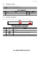
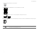
User manual | 8 1.1 Package contents The device package contents consist of the following: Note Please check all components involved. Table 1-1 Package contents No Name 1 Encoder 2 DC Power Adapter & Power cord 1.2 No 3 Name Quick guide Encoder description Refer to the diagrams below for buttons description and ports on the back of the encoder. 2 1 3 4 Figure 1-1 Name and Connection of each front section Table 1-2 Name and Function of each front section No.
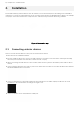
| Compressor™ Onvif Encoder 2. Installation Mount and install any external devices such as cameras, sensors and microphones according to the installation instructions. Connect the external devices to the encoder’s rear based on the diagram above. Below is an example of a proper connection between the Compressor, the cameras, and your remote monitoring software. Figure 2-1 Connection map 2.
User manual | 10 7 Connect a network cable to the network port. 8 Connect an alarm and RS485 devices to the terminal block as needed. 9 Connect a USB mouse to either one of the USB ports in front panel of the unit. 10 Once all external devices are connected properly, connect the encoder to an adequate power supply using the included cables. Note The encoder does not have a power button. The system boots up automatically upon connection to an external power source.
| Compressor™ Onvif Encoder 2.2 Starting the system Once all external devices have been connected to the back of the encoder, and the encoder has been added to the network properly, per the example above, power up the encoder and begin the quick setup wizard. 1 When the encoder boots up, it will be in protective mode. You will not be able to access the encoder’s setup menu until you login using the proper username and password. 2 To unlock the encoder, right-click anywhere on the screen.
User manual | 12 2.3.2 System 1 Adjust the system settings in this screen: Language: Select system language. Device Name: Enter the device name. Keyboard ID: Setup the encoder’s ID to match the ID settings of a keyboard controller. If you are controlling multiple encoders, setup different IDs for each encoder. HDMI / VGA: Set the resolution for the local monitor output connection. 2 Press Save button to save changes. 3 Press Next to end system settings. 2.3.3 Network 1.
| Compressor™ Onvif Encoder 3. Live Screen Configuration Below image is the encoder’s main UI. Figure 3-1 UI Screen Configuration Table 3-1 Items and Description of UI Screen Configuration No. Item Description 1 Setup menu Located on the top of the screen. See “4 Setup” for more information. 2 Live screen Shows live video for the connected cameras. 3 Launcher menu Located on the bottom of the screen. See “3.2 Live Launcher” for more information.
User manual | 14 3.1 Icons in live screen When viewing live video from the cameras connected to the encoder, a series of icons will display on the screen. Each representing a different setting or notification related to the selected channel. Note Chosen live screen is marked with a blue frame. Mouse-located live screen is marked as yellow one. Figure 3-2 Live screen icon Table 3-2 Live screen icon and its description No. Icon 1 CH1 CAM1 Description Channel numbers and camera titles.
| Compressor™ Onvif Encoder 3.2 Live launcher menu The launch menu is the main menu bar located at the bottom of the encoder’s screen. Figure 3-3 Launcher menu Table 3-3 Launcher menu Item and Description No. Item 1 2 Description Log in/out status and logged in ID. Date and time Displaying current date and time. 3 Move to previous/next split view screen or next single screen view.
User manual | 16 3.3 Quick menu The quick menu is available by right-clicking anywhere on the encoder’s screen. The available options are: Figure 3-4 Quick menu Table 3-4 Quick menu Item and Description No. Item Description 1 Screen mode Select the split view mode of live screen (single screen, 4-, 9-, and 16split view options). 2 Zoom in Digital zoom into a selected live screen (zoom out, 2x, 4x and 8x). 3 Freeze Freeze the video selected (toggle).
| Compressor™ Onvif Encoder 3.3.1 PTZ control For PTZ cameras connected to the encoder, use the PTZ control to move the camera and adjust settings as needed. Note To enable PTZ Control menu, go to DEVICE > PTZ in the upper live screen. Figure 3-5 Quick menu > PTZ control Table 3-5 Quick menu > PTZ control item and description No. Item Description 1 Move the camera’s view with direction buttons. 2 Move the camera’s view with PTZ ball. 3 AF Adjust screen focus automatically.
User manual | 18 In PTZ Control screen, right-click anywhereon the screen to open the PTZ quick menu options. Figure 3-6 PTZ control Quick menu Table 3-6 No. PTZ control’s quick menu Item and description Item Description 1 Preset, Tour, Scan, Pattern Run PTZ functions on supported models. 2 Exit Exit the PTZ quick menu and open the live view quick menu (PTZ mode still enabled) 3.3.2 Status > System log Users can see the system log information in System log tap in Status screen.
| Compressor™ Onvif Encoder 3.3.3 Status > Event When selecting Status from the quick menu options, users can see real-time event information for the unit. Figure 3-8 Table 3-8 No. Status > Event Item and Description in Quick menu Item 1 Status > Event Description Show or hide an event list (toggle). 2 Refresh Delete event list. 3 Event list Display event list. 4 Cancel Complete status screen.
User manual | 20 3.3.4 Status > Stream When selecting Status from the quick menu options, users can see the streaming information for the unit. Figure 3-9 Status > Stream Table 3-9 Status > Stream items and description No. Item 1 Input type 2 Main stream 3 Second stream Description Display input video type. Display main stream status. Display second stream status.
| Compressor™ Onvif Encoder 4. Setup menu Setup is available from the quick menu by right-clicking anywhere and selecting Setup.
User manual | 22 4.1 General buttons in setup menu Figure 4-2 General buttons in setup menu Table 4-1 Item and Description of General buttons in setup menu No. Item Description 1 Default Restore settings to their factory default. 2 Save Save changes to the encoder’s settings. 3 Cancel Cancel changes to the encoder’s settings. 4 Restore Cancel changes to the encoder’s settings and restore to the last saved values. 5 Apply Apply changes to the encoder’s settings.
| Compressor™ Onvif Encoder 4.2 SYSTEM 4.2.1 System Setup the system’s basic settings and update the firmware. Figure 4-3 SYSTEM > System > System Table 4-2 SYSTEM > System > System Item and Description No. Name Function 1 Language Set the system’s language. 2 Device name Enter the device’s name (English characters only). 3 Video type Select image standard types (NTSC or PAL). 4 Keyboard ID Select keyboard ID (1~255).
User manual | 24 4.2.1.1 System > F/W Upgrade Upgrade the system’s firmware. Figure 4-4 SYSTEM > System > F/W Upgrade Table 4-3 SYSTEM > System > F/W Upgrade Item and Description No. Name Function 1 Current version Display the firmware version currently installed. 2 Device Connect a USB memory with new firmware files to upgrade the system’s firmware.
| Compressor™ Onvif Encoder 4.2.2 Time/Date Set the date, time, and holidays of the system. 4.2.2.1 Time/Date > Time/Date Set the date, time, and holidays of the system. Figure 4-5 SYSTEM > Time/Date > Time/Date Table 4-4 SYSTEM > Time/Date > Time/Date Item and Description No. Name 1 System time Function Set the date and time. DST: select whether to use daylight saving time Time change: save changed time.
User manual | 26 4.2.2.2 Time/Date > Holiday Set specific days as holidays. These can later have their own settings, alarms and notifications. Figure 4-6 SYSTEM > Time/Date > Holiday Table 4-5 SYSTEM > Time/Date > Holiday Item and Description No. Name 1 Year 2 Function Select the year to set a holidays. Delete selected holiday. 3 Add holiday 4 List Add a holiday. Show the holiday list.
| Compressor™ Onvif Encoder When the “Add Holiday” button is selected, the following window will appear. Use the options to select the date, the type of holiday and when how will it repeat itself each year. Figure 4-7 SYSTEM > Time/Date > Holiday > Add Holiday Table 4-6 SYSTEM > Time/Date > Holiday > Add Holiday Item and Description No. Name Function 1 Name Enter the holiday’s name. 2 Date Display chosen date. 3 Type Select the holiday type.
User manual | 28 4.2.3 Account > User Add or modify user accounts and their access rights to the system. Figure 4-8 SYSTEM > Account > User Table 4-7 SYSTEM > Account > User Item and Description No. Name 1 Add group 2 Add user Add a new user. 3 Group list Display all groups. 4 User list 5 Live view Function Add a new users’ group. Display all users across all groups. Do not display live video if the system is not logged into a user.
| Compressor™ Onvif Encoder To add a new user group, press “Add Group”. The screen below will appear. You can setup the specific permission levels for this group on this page. You can allow all users assigned to the group access to live view, PTZ control, access to the setup menu, or firmware update rights. You can also assign specific channels or limit what channels users in the group can view. You must have at least one group setup to add users (see below).
User manual | 30 4.2.4 Configuration (Config.) In this menu, you can import and export settings or reset the system to its factory default settings. 4.2.4.1 Config. > Export/Import You can export the current system’s settings to a USB or import settings from a different system. Figure 4-11 SYSTEM > Config. > Export/Import Table 4-10 SYSTEM > Config. > Export/Import Item and Description No. Name 1 Device Function Select an exterior connector with USB. USB: displays the USB device connected.
| Compressor™ Onvif Encoder 4.2.4.2 Config > Factory Default Restore the system to its factory settings. Check the boxes next to the settings you wish to reset or click “Select All”. Click “Default” to confirm the reset. Figure 4-12 SYSTEM > Config > Factory Default Table 4-11 SYSTEM > Config > Factory Default Item and Description No. Name Function 1 Select all / unselect all Select all items to be defaulted. 2 Default item Select related items to be defaulted.
User manual | 32 4.3 CAMERA In the CAMERA menu, you can adjust the settings for the cameras connected with the device. 4.3.1 Basic Set the basic functions of camera and audio. 4.3.1.1 Basic > Basic Set the basic items for each channel. You can edit the channel’s title and set a channel as a covert channel. Figure 4-13 CAMERA > Basic > Basic Table 4-12 CAMERA > Basic > Basic Item and Description No. Name 1 CH 2 Title 3 Covert 4 Copy covert Setup Function Display the channel’s name.
| Compressor™ Onvif Encoder Press Copy Covert Setup button. The screen below will appear. Select which channel to copy the settings from. Check the boxes next to each channel you want to apply the same settings. Figure 4-14 CAMERA > Basic > Basic > Copy Covert Setup Table 4-13 CAMERA > Basic > Basic > Copy Covert Setup Item and Description No. Name 1 From 2 To 3 Select all / unselect all 4.3.1.2 Function Select a channel converted setting. Select a channel to be copied. Select all channels.
User manual | 34 4.3.2 Advanced Set camera video, stream and privacy mask settings for each channel. 4.3.2.1 Advanced > Scan Mode Use this screen to adjust the signal detected from the camera as needed. The system supported HD-Analog and HD-TVI. You can also setup the signal detection to auto, allowing the system to detect the signal automatically. Figure 4-16 CAMERA > Advanced > Scan Mode Table 4-15 CAMERA > Advanced > Scan Mode Item and Description No.
| Compressor™ Onvif Encoder Table 4-16 CAMERA > Advanced > Advanced Item and Description No. Name 1 CH 2 Video 3 Privacy mask Click the Editing Icon ( Function Display channels. Set brightness, contrast, and color of the camera. Set the privacy field; display field numbers set in parenthesis (setup up to 4 masks per channel). ) in the right corner, then Privacy Mask screen will be shown.
User manual | 36 4.4 DEVICE In the DEVICE menu, set the device’s display, PTZ settings and other external devices connected to the unit. 4.4.1 Display Set the system’s live screen display settings. 4.4.1.1 Display > Display Set the display settings. You can adjust the resolution of the local output monitor, enable pop-up event screens and enable a monitor relay switch. Figure 4-19 DEVICE > Display > Display Table 4-18 DEVICE > Display > Display Item and Description No.
| Compressor™ Onvif Encoder 4.4.1.2 Display > Spot Set the Spot output settings. Figure 4-20 DEVICE > Display > Spot Table 4-19 DEVICE > Display > Spot Item and Description No. Name 1 Sequence 2 Event popup Function Set the channel and dwell time (5, 10, 20, 30sec) when Auto mode is selected. Sets the hold time for full screen images of a channel when an event occurs (available options: off, 5, 10, 20, 30sec, continuous).
User manual | 38 4.4.1.3 Display > OSD Set the on screen display (OSD) settings. Figure 4-21 DEVICE > Display > OSD Table 4-20 DEVICE > Display > OSD Item and Description No. Name 1 Camera name 2 Live bar 3 Display icon Function Select the way to display camera in live screen (Off, CH+Title, CH). Select the way to display the live bar (always on, auto hide). Select what icons to display in the live screen.
| Compressor™ Onvif Encoder 4.4.1.4 Display > Sequence Setup a sequence view for the live display. Figure 4-22 DEVICE > Display > Sequence Table 4-21 DEVICE > Display > Sequence Item and Description No. Name Function 1 Quad sequence 2 Division 3 Sequence list Display the sequence list based on division selected. 4 Add sequence Add items to the play sequence. 5 NO. 6 Division 7 CH list 8 Dwell time 9 Default Set a sequence showing 4 channels at a time.
User manual | 40 Click on Add Sequence to add a new sequence. The screen below will appear. Select the channel, set the dwell time and the division type of the sequence (full screen or quad mode). Figure 4-23 DEVICE > Display > Sequence > Add Sequence Table 4-22 DEVICE > Display > Sequence > Add Sequence Item and Description No. Name 1 Dwell time 2 Division 3 Channel selection Function Select dwell time to show each channel (3 sec, 5 sec, 10 sec, 15 sec, and 30 sec).
| Compressor™ Onvif Encoder 4.4.2 PTZ > PTZ To use PTZ menu to setup PTZ enabled cameras. Figure 4-24 DEVICE > PTZ > PTZ Table 4-23 DEVICE > PTZ > PTZ Item and Description No. Name 1 Copy PTZ Setup 2 CH Channels number. 3 ID Select the camera’s ID (set from 1 to 255). 4 Protocol 5 Speed Note Function Apply setting from a selected channel to multiple channels. Select protocol of the camera connected to the selected channel.
User manual | 42 4.4.3 Serial Device > Serial Device Setup a serial device connected to the system such as PTZ cameras and USB devices. Figure 4-25 DEVICE > Serial Device > Serial Device Table 4-24 DEVICE > Serial Device > Serial Device Item and Description No. Name 1 USB (to serial) 2 RS-485 Function Set communication transmission value of USB device. Set communication transmission value of RS-485 connector.
| Compressor™ Onvif Encoder 4.5 EVENT In the EVENT menu, users can setup notifications, alarm and sensors, video loss and motion detection. 4.5.1 System Set the system events that would trigger alarms. 4.5.1.1 System > System Set the system event of the device Figure 4-26 Event > System > System Table 4-25 Event > System > System Item and Description No. Name 1 System restart 2 Notification 3 User login Function Enable system reboot as an event.
User manual | 44 4.5.2 Alarm In Set sensor alarms and schedule 4.5.2.1 Alarm In > Setup Set sensor alarms Figure 4-27 Event > Alarm In > Setup Table 4-26 Event > Alarm In > Setup Item and Description No. Name Function 1 Sensor 2 Use Enable a sensor. 3 Type Select sensor types (N.O, N.C). 4 Beep Set a beep sound when a sensor is activated. Select from the available length options (null, 5 sec, 10 sec, 20 sec, 30 sec, 1 min, 10 min, 30 min, and 1 hour).
| Compressor™ Onvif Encoder Click on the editing Icon ( ) next to Alarm, Group Rec, Noti., Preset to show the following screen: Figure 4-28 Event > Alarm In > Setup > Event: Alarm Table 4-27 Event > Alarm In > Setup > Event: Alarm Item and Description No. Name 1 Alarm-out Function Set the alarm. • Relay: enable a relay output when an event occurs.
User manual | 46 4.5.2.2 Alarm In > Schedule Setup a schedule when sensors are active. You can setup individual schedules for each sensor connected to the encoder, or copy and apply the same schedule to all devices. Figure 4-29 Event > Alarm In > Schedule Table 4-28 Event > Alarm In > Schedule Item and Description No. Name Function 1 Sensor 2 Schedule type Select the types of schedules. If None is selected, the sensor will be disabled.
| Compressor™ Onvif Encoder 4.5.3 Motion Set and schedule motion detection for each of the system’s channels. 4.5.3.1 Motion > Setup Set motion detection Figure 4-30 Event > Motion > Setup Table 4-29 Event > Motion > Setup Item and Description No. Name 1 CH Show channel’s number. 2 Use Enable motion detection for each channel. 3 Area Display the motion detection area. 4 Sens. Select the sensitivity level for motion detection (Level 1~10).
User manual | 48 4.5.3.2 Motion > Schedule To schedule record time when the motion sensor detects across channels Figure 4-31 Event > Motion > Schedule Table 4-30 Event > Motion > Schedule Item and Description No. Name Function 1 CH 2 Schedule type Select the types of schedules. If None is selected, the motion detection will be disabled. 3 Schedule table Displays the operating schedule for the selected channel.
| Compressor™ Onvif Encoder 4.5.4 Video Loss > Setup To set Video Loss across channels Figure 4-32 Event > Video Loss > Setup Table 4-31 Event > Video Loss > Setup Item and Description No. Name 1 CH Show channel’s number. 2 Use Enable video loss event for each channel. 3 Beep Set a beep sound when video loss is detected. Select from the available length options (null, 5 sec, 10 sec, 20 sec, 30 sec, 1 min, 10 min, 30 min, and 1 hour).
User manual | 50 4.5.5 Notification Set and schedule notifications for alarms and events. 4.5.5.1 Notification > Periodic Set a periodic alarm. This alarm will go out to an e-mail every set amount of time with information about a selected channel’s events. Figure 4-33 EVENT > Notification > Periodic Table 4-32 EVENT > Notification > Periodic Item and Description No. Name Function 1 Periodic notification Enable periodic alarms. 2 Summary Send event information.
| Compressor™ Onvif Encoder 4.5.5.2 Notification > Schedule Schedule remote notification (alarm and motion) Figure 4-34 EVENT > Notification > Schedule Table 4-33 EVENT > Notification > Schedule Item and Description No. Name Function 1 Schedule type Select the types of schedules. If None is selected, notifications will be disabled. Select green to enable e-mail notifications, blue for push mobile notification or purple to enable both.
User manual | 52 4.6 NETWORK In the NETWORK menu, users may set the network environment. Please contact your network administrator for more information. 4.6.1 Basic > WAN Port Set the system’s network environment Figure 4-35 NETWORK > Basic > WAN Port Table 4-34 NETWORK > Basic > WAN Port Item and Description No. Name Function 1 Static IP 2 DHCP (Dynamic) 3 MAC address 4 DNS 5 Port (TCP) Enter the TCP port information. 6 Port (web) Enter the web port information.
| Compressor™ Onvif Encoder 4.6.2 DVRNS/DDNS Set DVRNS/DDNS 4.6.2.1 DVRNS/DDNS > DVRNS/Dashboard Register a DVRNS/Dashboard account Figure 4-36 NETWORK > DVRNS/DDNS > DVRNS/Dashboard Table 4-35 NETWORK > DVRNS/DDNS > DVRNS/Dashboard Item and Description No. Name 1 DVRNS Function Register a DVRNS account • ID: enter DVRNS ID (default: MAC address of the unit). • Password: enter DVRNS password. • Register: register DVRNS account.
User manual | 54 4.6.2.2 DVRNS/DDNS > DDNS Set a DDNS site for remote users to access Figure 4-37 NETWORK > DVRNS/DDNS > DDNS Table 4-36 NETWORK > DVRNS/DDNS > DDNS Item and Description No. Name Function 1 DDNS site Select DDNS site from the available options. 2 Host name Enter the host name. 3 User name Enter the user name. 4 User password Enter the user password.
| Compressor™ Onvif Encoder 4.6.3 E-Mail Set an e-mail server to send e-mail notifications when events occur. Figure 4-38 NETWORK > E-Mail > E-Mail Table 4-37 NETWORK > E-Mail > E-Mail Item and Description No. Name 1 Server type Function Select an SMTP server. • • • • • 2 Address / port 3 Image attach 4 Authentication 5 ID 6 Password 7 Sender 8 Receiver 9 Test gmail.com hotmail.com aol.com naver.com daum.com Enter the server address and port number.
User manual | 56 4.6.4 4.6.4.1 Notification Server Notification Server > Notification Server Setup a notification server. When an event occurs, a notification will be sent to a server. Figure 4-39 NETWORK > Notification Server > Notification Server Table 4-38 NETWORK > Notification Server > Notification Server Item and Description No. Name 1 Notification server 2 Type 3 IP 4 Port 5 Test Function Select/deselect whether to use notification server. Select TCP or UDP protocol.
| Compressor™ Onvif Encoder 4.6.4.2 Notification Server > Notification Message Set up a message to be sent to the notification server when event occurs. Figure 4-40 NETWORK > Notification Server > Notification Message Table 4-39 NETWORK > Notification Server > Notification Message Item and Description No. Name 1 Function Deleted registered notification message. 2 Add 3 CH 4 Event 5 Message Notification message edit window pop-up. Camera channel.
User manual | 58 5. Web viewer This chapter describes web viewer for monitoring video form the device through a PC in remote mode. 5.1 How to monitor with web viewer Table 5-1 System Requirement for Web viewer Item Recommended OS Microsoft® Windows® 10 x86 (64bit) (Home Premium, Professional, Ultimate) Minimum Microsoft® Windows® XP Home SP3 Microsoft® Windows® 8 (pro, Enterprise) 1 CPU Intel Core™ i5-2550 3.
| Compressor™ Onvif Encoder 5.1.1 In case of selecting Viewer (Internet Explorer) 1 Click Viewer. 2 When Java download screen opens, download and install JAVA. 3 Live images may be monitored. In case of selecting Viewer (Chrome) 1 After click Viewer, .jnlp file can be downloaded. Click Keep button.
User manual | 60 2 Click webviewer_chrome.jnlp. 3 When Java download screen opens, download and install JAVA. 4 Live images may be monitored. 5.1.2 In case of selecting Setup Users can set the menu in similar ways with local connected monitor.
| Compressor™ Onvif Encoder 6. Products Specifications VIDEO Video input Video out Signal type HD-Analog, HD-TVI and analog signal up to 960H CH# 16CH BNC input Outputs and True HD / VGA: 1920x1080, 1280x720, 1024x768 Resolutions Spot: 1.0 Vp-p (75 ohm, Composite) True HD/VGA: 1/4/9/16 Split, PIP, Sequence Display mode Spot: 1/16 Split, Sequence Compression H.264 Main stream: 240fps @ 2.
User manual | 62 GENERAL Operating temperature and 32°F ~ 113°F (0°C ~ 45°C) humidity Less than 90% (non-condensing) Other certifications FCC Electrical Power requirement 12V DC, 2A Power consumption Max. 14.4W, 1.2A Dimensions 14.76" x 1.76" x 12.52" (375 x 44.9 x 318.2 mm) Weight 3.96lbs (1.8kg) ※ Specifications are subject to change without notice.