Installation Manual for the Duet Range: D2600 Duet2 D2650 Duet3 Dycon Ltd Cwm Cynon Business Park – Mountain Ash – CF45 4ER – UK Tel: +44 (0)1443 471 060 Fax: +44 (0)1443 479 374 www.dyconsecurity.eu sales.en@dyconsecurity.
TABLE OF CONTENTS 1. 2. Description Part Numbers p.3 p.4 3. 4. 5. 6. What to Do: Site Survey Installation System Testing Troubleshooting / Help Desk p.5 p.6 p.6 p.7 7. 8. 9. 10. 11. 12. 13. 14. 15. 16. 17. 18. 19. 20. 21.
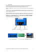
Installation Manual for D2600 Duet2 and D2650 Duet3 1. Description The Duet is an advanced auto-dialling digital communication device for adding GPRS, GSM, SMS and LAN reporting to control panels that have a telephone line connection. The Duet monitors the telephone line that is normally connected to the control panel’s digi-modem. If a line fault is detected, the Duet sends a line fault alarm to the Alarm Receiving Centre on its radio path.
2.
3. Site Survey It is strongly recommended that a site survey is conducted prior to the installation of a Duet to confirm that adequate GPRS signal strength is available at the site. If there is no GPRS radio coverage at the proposed site, the Duet radio alarm reporting path will not operate. You can use a Duet, aerial and fully charged battery to survey the proposed site for the point of strongest signal. See Aerial Siting on Page 13 for more information.
4. Installation 1. Site the aerial at the point of strongest signal ensuring that it is within the protected area. This is usually the highest point in the building and well away from metal roofs and metal walls (use Dycon D2366 Test Set). See Page 13. 2. Program the NVM for the system specific requirements using the D2454 Programmer software. See page 18. 3. Obtain a GPRS-enabled SIM card from your GSM Service Provider. 4. Totally power down the control panel mains and battery. 5.
System Testing (cont’d) 3. To confirm correct operation, trigger a call to the ARC by setting the control panel so that it sends a ‘Close’ signal. With the telephone line connected, the signal should go to the ARC via the telephone line. Disconnect the telephone line. The Duet should detect this and send a “PSTN Fail” signal to the ARC via the GPRS radio path. Unset the control panel. The ‘Open’ should go to the ARC via the GPRS radio path. 4. Contact your ARC to confirm that all signals have been received.
7. Operation The basic operation of the Duet is to intercept communication activity from the alarm control panel or other digital communication device (Digicom) to the PSTN and redirect it to 1 or more locations using 1 or more signalling paths. The signalling paths can be WIRED (PSTN, LAN) or RADIO (GSM, GPRS, SMS). The Duet performs the following functions: 7.1 1.
Call Interception (cont’d) 7.1.1.2 Forward before Acknowledge In this case, the Duet will attempt to forward the call before sending an “acknowledge” to the alarm control panel. This will cause the alarm control panel to make several attempts to call the Duet. If the alarm control panel has many Contact ID messages to send, they will be forwarded very slowly, one call forwarded at a time, rather than using the “follow-on” call technique. This operation may be improved by using a third technique.
7.3 Line Monitoring The Duet will constantly monitor the programmed paths for integrity. Should the PSTN path fail, for example, the Duet will construct a 'PSTN Line Fail' message, using programmable details, and pass this data message into the NVM for processing. Similarly if any other path should fail a suitable message will be constructed and passed to the NVM. Please refer to the Test Call and Line Monitoring NVM strings in 7.4.3 below.
Test Call, Line Monitoring and NVM Input Data (cont’d) 7.4.3.1 For Fast Format the string should contain the channel number. For 8-channel reporting, this should be a single digit. For 16-channel reporting, this should be 2 digits. Examples: Message 8 Channels 16 Channels Test Call PSTN Line Fail GSM Line Fail Input 1 Input 2 9 6 7 1 2 17 16 15 01 02 Input 3 Input 4 3 4 03 04 Notes (Fast Format): 1.
Notes (Contact ID Format): 1. The 4, 5 or 6 digit account number, the Contact ID identifier '18' and the Alarm/Restore digit ('1' or '3') will precede these codes. 2. The checksum will be calculated and appended to the data. 7.4.3.3 For SIA Format the string should contain 2-letter SIA event code, plus any partition, zone or user information, up to a maximum of 8 characters. The SIA restore letters are programmed into another column.
12. NVM Programmable Options Please refer to the Duet’s NVM specifications, being the definitive reference on the NVM programming details. The maximum call log size, using 93C86 NVM, is 63 events. 13. Engineer Receiver Function An engineer receiver function exists in the Duet whereby it can receive calls on the GSM network, handle them as if they came from an alarm control panel, and put them into the NVM for further processing.
15. SIM Card A suitable GPRS/GSM SIM card may be obtained from your GSM service provider. Check if a GSM SIM card has already been fitted by your Duet supplier. Ensure that the SIM Card is enabled for ‘Data’ and ‘GPRS’. The Duet will not send alarms if enabled for ‘Speech Only’. Ensure that the SIM card is enabled for incoming and outgoing SMS messages. The Duet will not send SMS messages if ‘outgoing SMS messages’ are not enabled. The SIM card has a number printed on it.
18. SMS Messages SMS commands may be in upper or lower case. Upper case is shown in these examples for clarity. Should an invalid message be received, a reply to the sending phone will be sent, informing them of the fault. Other status messages may be sent to the Duet. A full list of the available SMS messages can be found in Appendix 2. If ‘SMS confirm’ is not ticked in the D2454 programmer, confirmation SMS messages will not be sent to the calling phone.
18.4 Remote Reset This is a specific command to operate Output 4. Output 4 timer should be set for 3 seconds duration. The format of the command is ‘RR’. It operates in exactly the same way as the commands ON 4, or 141, or O 4 ON. A reply will be sent to the calling phone: Duet: Remote Reset. 18.5 SMS number change Sending the keywords SMS1 or SMS2 will cause the Duet to extract the calling phone’s number from the incoming SMS message and store it in SMS number 1 or 2. (SMS0 will store it in both).
18.11 Call the Download Server Sending the keyword CALL will result in the Duet calling the Download Server. The Download Server’s IP address and port must have been pre-programmed into the ‘Callback’ number of the Duet. GPRS and/or wired download must have been enabled in the Duet. If the call cannot be made by virtue of NVM parameters not being correct, the message ‘Callback disabled’ will be sent to the calling phone, otherwise the message ‘Calling Downloader’ will be sent. 18.
19.2 Operation On the metal boxed socket, where the LAN cable connects are yellow and green LEDs. When properly connected, the yellow LED will be on solidly and the green LED will blink on once every 1-2 seconds. Note: Any extra inputs or outputs on the LAN card are not available for use with the Duet. The 4 inputs and 4 outputs are on the Duet’s main board. 20. System Power Supply and Battery The Duet requires a supply of 12-13.
21.1 21.2 Calling 1. Two IP addresses for GPRS alarm calls 2. Two IP addresses for LAN alarm calls 3. Two GSM Numbers for alarm reporting 4. One GSM Number, or IP address, for Secure Callback 5. Two SMS phone numbers 6. Two IP addresses for polling over GPRS 7. Two IP addresses for polling over LAN Automatic Test Calls Periodic test calls can be sent at intervals of 1 to 99 seconds, minutes, hours or days. These timings may be selected as Dynamic (i.e. since the last call), or Static (i.e.
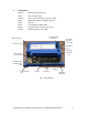
APPENDIX 1 LED Indications The Signal Strength LEDs are Red and Green. See Fig 6, page 22. When the Duet is not triggered, these give an indication of the GSM radio signal strength received at the Duet. A ‘once per second’ short off-blink shows all is OK. The Signal Strength LEDs will give a signal strength indication after the Duet has been powered for 30 seconds.
APPENDIX 1 LED Indications (cont’d) The Radio Communication LED is Yellow. See Fig 6, page 22.
APPENDIX 1 LED Indications (cont’d) The PSTN LED is Red. See Fig 6, page 22. LED off PSTN disabled in NVM programming, or enabled but no PSTN line activity and no PSTN faults detected LED on solid Ringing flashes in sync with the ringtone 1 flash 2 flashes On line Incoming ringing is detected and this may inhibit the Duet from making a telephone call PSTN telephone line DC voltage is very low or absent Another phone (or fax, etc.
APPENDIX 2 SMS Command Table Function Security Code 123456 Text Command Software Version Test Call 123456 VER 123456 TEST Remote Reset 123456 RR Reset 123456 RESET Call Downloader 123456 CALL Output n ON 123456 O n ON Output n OFF 123456 O n OFF All outputs ON 123456 O 0 ON Several outputs ON 123456 ON 134 SMS number change 123456 SMSn Status Numerical Notes Command Data Unit will respond with SMS message showing system status.
APPENDIX 2 SMS Commands Table (cont’d) Function IP address change Security Code 123456 Text Command Numerical Command Data 30 172.16.1.2 IP address change 123456 3n IP address change 123456 40 IP address change 123456 4n IP port change 123456 50 IP port change 123456 5n IP port change 123456 60 IP port change 123456 6n Telephone number change 123456 7n Callback number change GSM number change 123456 77 123456 8n Notes Change all GPRS IP addresses to the given one.
APPENDIX 2 SMS Command Table (cont’d) Function Invalid Command Invalid Security Code Security Text Code Command 123456 Anything not listed above Numerical Command Data 654321 Notes Unit will respond with SMS message showing: INVALID COMMAND Unit will respond with SMS message showing: INVALID CODE Notes: The security code must be 6 digits in length. The text command OR the numeric command + data may be used. The fields ‘security code’, ‘command’ and ‘data’ may be separated by zero or more spaces - e.g.
APPENDIX 3 ADSL (Asynchronous Digital Subscriber Line) or ‘Broadband’ When an analogue PSTN telephone line also carries ADSL (Broadband) signals and it is used by a security system e.g. the Duet, then a Security ADSL filter MUST be used. A filter is used to separate the analogue telephone signals from the ADSL (broadband) digital data signals because the phone or security system may be disrupted or completely inhibited if ADSL (broadband) digital data is allowed into them from the telephone line.
APPENDIX 3 ADSL (Asynchronous Digital Subscriber Line) or ‘Broadband’ Analogue and ADSL service provided by the Network Service Provider ADSL filter and security equipment in a tamper protected enclosure Duet PSTN Connection using the D0730 Security ADSL Filter Fig 8 Q. Why is a Broadband Filter necessary? A. When ADSL (broadband) digital data is supplied on a normal PSTN telephone line then...
APPENDIX 4 Specification Models D2600-B Duet2 D2650 Duet3 Dimensions (h x w x d) 25 x 175x 120 mm Weight 200 grams Telephone Path PSTN technology, CTR21 approved Radio Path GSM Power Requirement 12.0 - 13.8volts DC, 0.1volt max ripple Current Consumption 60mA quiescent, 100mA operating Low Battery 10.8-11.0 volts falling, 11.8-12.
APPENDIX 5 European PSTN Approval The Duet product range meets the requirements of the EU PSTN standard CTR21 and is approved for connection to any exchange line forming part of a Public Switched Telephone Network (PSTN). AHCTR210 001 Declaration of Network Compatibility The equipment has been approved in accordance with Council Decision 98/ / EC (5) for pan-European single terminal connection to the Public Switched Telephone Network (PSTN).
APPENDIX 6 Glossary of Terms ADSL Asynchronous Digital Subscriber Line A ‘wideband’ digital communication service from a network provider to a subscriber that carries a high volume of digital data, most commonly for internet access. Sometimes called ‘broadband’. An ADSL service is often provided with a simultaneous analogue PSTN service on a hybrid line. Analogue PSTN Analogue Public Switched Telephone Network The analogue national telephone system. Often just called the PSTN.
APPENDIX 6 Glossary of Terms (cont’d) DTMF Fast Format Dualcom96 EEPROM GSM GPRS Hybrid Line NTP NVM PABX PSTN SMS SMS Message Centre Alarms Reporting Protocol A protocol that is a sequence of analogue tones (push-button telephone tones) used to send via telephone lines a transmission to receiving equipment at an ARC, and to receive checking and acknowledgement replies from that receiving equipment. 8 or 16 channel DTMF Fast Format protocol is commonly used in burglar or intruder alarm equipment.
APPENDIX 6 Glossary of Terms (cont’d) Terminal Adapter WEB SITE 3-Way-Calling A device that connects to the S-bus connection of an ISDN Network Termination Point and adapts the digital S-bus data, i.e. protocol, data speed, structure, to that required. E.g. the conversion may be to analogue PSTN or to a serial port for cable connection to a PC serial ‘COM’ port. The Dycon Internet Web Site The Dycon web site: www.dyconsecurity.com contains the latest copies of all manuals for all Dycon products.