
User`s manual


VC-55™ PR Voice Codec Board
User’s Manual
Version 1.3
Section 3 – Set-up & Control
Page 13
DVSI Confidential Proprietary
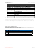
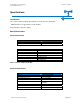
board.
Encode_Mode APCO (Full Rate) Half-Rate (Half-Rate)
Slip_Mode 1 (Slip Mode On) 0 (Slip Mode Off)
EncodeCmode 0(NS & DTX off); 64(NS on); 2048 (DTX on); 2112 (NS & DTX on)
Chan_Rx_Min_Time 0 -636 (The jitter buffer delay as set in the parameters)
Chan_Rx_Max_Time 4 - 640 (The jitter buffer delay as set in the parameters)
Encode_Source 1 (Handset) 2 (Line –In)
Channel_Uart_Rate 20 – 240 (115,200 to 9,600 as set in the parameters)
Sync_Err_Rate Sync error rate is the bit error rate in the sync and rate words of the
packet multiplied by 512
Lost_Sync_Rate The number of times the channel has lost sync
Lost_Packets The number of packets not received from across the channel. This
could be due problems in the channel or for clock drift between the
two systems.
Dropped_Packets The number of packets that got dropped and not processed by the
decoder because it could not keep up with the input.
DecodeErrRate estimated bit error rate in FEC protected bits of packet *2^17
Table 6 vc55param output to screen
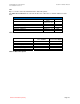
Executing the vc55param program without setting any of the parameter options will result in a print to
screen of all the current settings information stored in the VC-55™ -PR Vocoder Board ‘s flash memory.
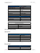
VC-55™ -PR Vocoder Board Status
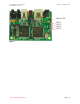
The VC-55™-PR Vocoder Board has five LED’s that are designed to indicate the current status of the
vocoder and the communications channel to the operator.
LED ID Description
PWR The LED is ON when Power is Applied
LED 1 The LED is ON when there are no lost Packets
LED 2 The LED is ON during the time the Encoder is not encoding samples
LED 3 The LED is ON during the time the Decoder is not decoding samples
LED 4 The LED is ON when the Channel has Lost Synchronization
Table 7 Status LED's