
User`s manual

VC-55™ PR Voice Codec Board
User’s Manual Version 1.3
Section 2 – Installation
Page 7
DVSI Confidential Proprietary
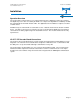
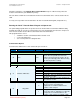
Connecting two Boards together via UART
Establishing a real-time, full-duplex communication link between two boards is as easy as connecting a
cable directly between the two units. The VC-55™- PR Vocoder Board implements an asynchronous
RS-232 serial interface for channel data using a protocol designed by DVSI. Analog voice from one
VC-55™- PR Vocoder Board is encoded and sent through the RS-232 channel interface to another VC-
55™- PR Vocoder Board. Incoming channel packets from RS-232 are decoded and played out on the
handset of the second VC-55™- PR Vocoder Board. Once the link is established voice communication
for each board can be made through either the handset or stereo phono plug line input.
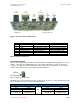
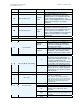
Cable pinout for UART Asynchronous Serial Port
RJ45 Connector End 1 RJ45 Connector End 2
Pin Number Signal Name Signal Name Pin Number
1 Not Connected Not Connected 3
2, 5, 6, 8 Ground Ground 2, 5, 6, 8
7 Tx Channel out Rx Channel In 4
3 Not Connected Not Connected 1
4 Rx Channel In Tx Channel out 7
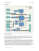
Figure 4 Connecting two VC-55™-PR Vocoder Board’s together
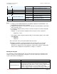
Connecting the UART Serial Connection to another device
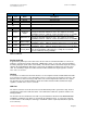
Serial Port Settings
Bits per second: 115,200
Data bits: 8
Parity: None
Stop bits: 1
Flow control: None
Table 4 UART Serial Port Settings