
User`s manual

VC-55™ PR Voice Codec Board
User’s Manual Version 1.3
Section 2 – Installation
Page 6
DVSI Confidential Proprietary
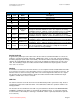
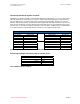
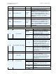
J7 Analog Audio I/O
Pin # I / O
Function
Name
Description
3, 4, 7, 8 Ground Analog Ground
9, 10, 21, 22, 29,
30
Ground Digital Ground
16, 18 Output 3v3 3.3 Volts Supply
1 Output
Audio Out
Right
The analog speech output produced by passing the decoder output
through the 16 bit AIC-23B linear codec. The output has an analog
bandwidth of 100 Hz. - 3600 Hz., and it is maximum level is 1.0 volt RMS.
2 Output Audio Out Left
The analog speech output produced by passing the decoder output
through the 16 bit AIC-23B linear codec. The output has an analog
bandwidth of 100 Hz. - 3600 Hz., and it is maximum level is 1.0 volt RMS.
5 Input Audio In Right
Analog speech input to the encoder via AIC23B linear codec has a
bandwidth of 20 Hz. - 4000 Hz. Maximum input level is 1.41 Volts RMS.
6 Input Audio In Left
Analog speech input to the encoder via AIC23B linear codec has a
bandwidth of 20 Hz. - 4000 Hz. Maximum input level is 1.41 Volts RMS.
23 Input Encode_Mode
When this pin is set to the low state (default) the vocoder will run in Half-
Rate mode @ 2450bps. When this pin is set high the vocoder will
operate in Full-Rate mode @ 4800bps.
Table 3 J7 Pinout
Analog Audio I/O
A typical analog audio input connection for the VC-55™- PR Vocoder Board would be to connect the
audio Line out output of an audio component, a Digital Tape, player or even a PC sound card output to
the Analog Input jack (audio cables not included). The VC-55™- PR Vocoder Board outputs the analog
signal on the output RCA jack that may be connected to an amplifier or Audio In jack on a PC sound
card. The unit always outputs the audio to both the 4-Wire and Handset output regardless of which
voice source is selected.
Handset
If a handset is used instead of the 4 wire interface, use the telephone handset included with the board’s
accessory kit (to assure the correct microphone levels) to connect to the RJ11 handset connector. The
handset cord is less than a foot long to help reduce noise from being introduced into the voice signal.
The VC-55™- PR Vocoder Board always outputs the audio to both the 4-Wire and Handset output
regardless of which voice source is selected.
USB Port
The USB 2 connection on the VC-55™- PR Vocoder Board unit provides system boot setup, mode of
operation and control of the audio I/O via PC. The USB interface allows the operation software to be
field upgradeable.
The VC-55™- PR Vocoder Board comes with easy to install drivers that work under WinXP Win2000
and Win98. Installation of the drivers is described in the following Section. To connect the VC-55™
Vocoder Board to a PC USB port a USB “Type A to Mini-B” cable is required (included in the optional
accessories kit).