
User`s manual

VC-55™ PR Voice Codec Board
User’s Manual Version 1.3
Section 2 – Installation
J
5
Handset
J1
Audio
Out
J2
Audio
In
J3
USB
J6
RS-232
J7
Analog Audio I/O
J11
Digital I/O
J10
Power
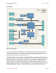
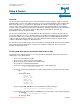
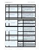
Figure 2 VC-55™- PR Vocoder Board Top
Board Top Connections
Item Name Connector Type Description
J6 Serial Port RJ-45 Channel Data
J3 USB* Type Mini-B Receptacle Control / Program / File IO
J2 Analog Line In 3.5mm Audio Jack Audio from Line In
J1 Analog Line Out 3.5mm Audio Jack Audio out to Spkrs / amp
J5 Handset RJ-11 Full Duplex Communication
J10 DC Line In Power Receptacle 5 Volts DC
Table 2 Top Panel Connectors
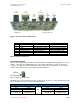
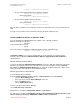
Connecting DC Power
The user must supply the VC-55™-PR Vocoder Board with a 5 V digital power supply There are no user
settings. Just plug in the 5V DC 250ma power source into the DC power receptacle on the board
receptacle (See Table 2 Top Panel Connectors item 9). DVSI offers an optional accessories kit that
contains a AC to DC converter for the VC-55™-PR Vocoder Board.
+5Volts
DC Ground
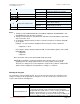
Figure 3 Power Input Connection
The OEM version of the board has the Power connections located on J11. The board will operate with
either 3.3 V DC or 5.0 V DC as shown in the following table:
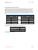
Bottom Connector J11
5.0 V DC Power 3.3 V DC Power
Pins Name Pins Name
6,8 5.0 V DC Input
or
2,4 3.3 V DC Input
1, 3, 5, 7, 13, 14,
21, 22 ,29 ,30
Digital Ground
1, 3, 5, 7, 13, 14, 21,
22 ,29 ,30
Digital Ground
Note: Do not apply both the 5V DC and 3.3 V DC power at the same time.
Page 5
DVSI Confidential Proprietary