
User`s manual

VC-55™ PR Voice Codec Board
User’s Manual Version 1.3
Section 2 – Installation
Block Diagram
DIO
CHAN1
CHAN2
IO
Sys Clock
2 Channe l Aud io Interface
J7
J11
J1
J2
J3
J5
J6
J8
J10
Ext 5V
Connector
Voltage
Regulators
Power Mux
6.144 MHz.
Crystal
FPGA
Boot Config
Header
Flash
DSP
(C5509A)
USB
Connector
RS-232
Channel
RJ45
Digital I/O Analog & Digital I/O
Analog Out
Stereo Jack
Analog In
Stereo Jack
18.432 MHz.
Synthesizer
Stereo Codec
(TLV320AIC23B)
RS-232
Transceiver
HandSet
RJ11
12 MHz.
Crystal
VC-55 -P25-EDR
Block
Diagram
™
3. 3 Volt Input
5. 0 Volt Input
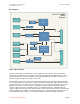
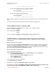
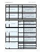
Figure 1 Block Diagram
To meet a wide variety of communication system requirements the VC-55™- PR Vocoder Board
contains two analog interfaces for real-time speech input and output and an USB interface for set-up
and control from a PC. The VC-55™-PR Vocoder Board analog interface includes a 4-wire and a
handset for input and output of uncompressed speech.
For the channel connection, the VC-55™ Vocoder Board provides an asynchronous RS-232 interface
for connecting directly to a serial device or another VC-55™ Vocoder Board. When two VC-55™-PR
Vocoder boards are connected together to communicate, each converts the input analog speech into
digital speech samples, encodes the speech using the selected vocoder rate and then sends the
compressed bit stream out as serial data packets over the RS-232 interface. Simultaneously, the
compressed bit stream from the other VC-55™-PR are read in from the RS-232 interface and decoded
back in to digital speech samples. The decoded samples are converted back into analog speech via
the AIC-23B codec whose output is sent to both the handset and line-level output connections.
Page 4
DVSI Confidential Proprietary