Digital Voice Systems, Inc. The Speech Compression Specialists VC-55™-PR Voice Codec Board User’s Manual Version 1.
VC-55™-PR Voice Codec Board User’s Manual Version 1.3, February 2015 Copyright, 2005 Digital Voice Systems, Inc 234 Littleton Road Westford, MA 01886 This document may not, in whole or in part be copied, photocopied, reproduced, translated, or reduced to any electronic medium or machine readable form without prior consent in writing from Digital Voice Systems, Incorporated. Every effort has been made to ensure the accuracy of this manual. However, Digital Voice Systems, Inc.
VC-55™- PR Voice Codec Board END USER License Agreement 1. Preliminary Statements and Definitions 1.1 This nonexclusive end user product license agreement is a legal agreement between the customer (the END USER) and Digital Voice Systems, Inc. (DVSI) covering the terms and conditions under which DVSI's proprietary content (that may consist of and is not limited to software, hardware, documentation and other material) is licensed to the END USER as part of this PRODUCT.
Net-2000™ VCU Users Manual Version 1.3, February 2015 the PRODUCT. Some states do not allow the exclusion of implied warranties, so the above exclusion may not apply to END USER. No oral or written information or advice given by DVSI or its employees shall create a warranty or in any way increase the scope of this warranty and END USER may not rely on any such information or advice.
VC-55™ PR Voice Codec Board User’s Manual Version 1.3 Information – Section Special Handling Instructions To avoid damage from the accumulation of a static charge, industry standard electrostatic discharge precautions and procedures must be employed during handling and installation the VC-55™-PR Vocoder Board. 1. Read Instructions and Users Manual – All of the safe handling and operating instructions should be read before integration of the VC-55™- PR Vocoder Board begins.
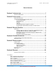
VC-55™ PR Voice Codec Board User’s Manual Version 1.3 Section – Table of Contents Table of Contents Section 1 INTRODUCTION .....................................................................1 GENERAL INFORMATION .........................................................................................1 Section 2 INSTALLATION ......................................................................3 OPERATION OVERVIEW .........................................................................................
VC-55™ PR Voice Codec Board User’s Manual Version 1.3 Section – Table of Contents TABLE 10 RATES DESCRIPTION ............................................................................................ 16 TABLE 11 RS-232 SERIAL PORT PIN OUT ............................................................................ 17 TABLE 12 RS-232 SERIAL PORT PIN OUT ............................................................................ 18 List of Figures FIGURE 1 BLOCK DIAGRAM .................................
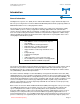
VC-55™ PR Voice Codec Board User’s Manual Version 1.3 Section 1 – Introduction Introduction Digital Voice Systems, Inc. The Speech Compression Specialists General Information The Digital Voice Systems, Inc. (DVSI) VC-55™- PR Vocoder Board is a single channel full-duplex realtime voice processing board. The VC-55™-PR Vocoder Board implements DVSI’s proprietary Advanced Multi-Band Excitation™ voice coding algorithm software.
VC-55™ PR Voice Codec Board User’s Manual Version 1.3 Section 1 – Introduction under all tested conditions. These superior performance characteristics make the enhanced vocoders ideal for use in any digital communication application where bandwidth is at a premium and high quality voice is imperative. The VC-55™- PR is an economical hardware solution for customers who want to gain access to the APCO Project 25 (P25) land mobile radio vocoder technology.
VC-55™ PR Voice Codec Board User’s Manual Version 1.3 Section 2 – Installation Installation Digital Voice Systems, Inc. The Speech Compression Specialists Operation Overview The VC-55™-PR vocoder board uses an on-board A/D converter to digitize the analog speech input. The digitized speech is then encoded by the DVSI voice compression algorithm into a 7200 bps or 3600 bps serial data bit stream which includes FEC. The digital data is then available for output to a modem or similar device.
VC-55™ PR Voice Codec Board User’s Manual Version 1.3 Section 2 – Installation Block Diagram VC-55™-P25-EDR Block Diagram USB Connector Boot Config Header DSP (C5509A) 12 MHz. Crystal J3 Flash DIO J7 RS-232 Channel RJ45 J6 Analog In Stereo Jack RS-232 Transceiver Analog & Digital I/O J8 CHAN1 CHAN2 FPGA IO 18.432 MHz. Synthesizer Sys Clock J2 Analog Out Stereo Jack 6.144 MHz.
VC-55™ PR Voice Codec Board User’s Manual Version 1.3 Section 2 – Installation J5 Handset J6 RS-232 J10 Power J3 USB J11 Digital I/O J2 Audio In J1 Audio Out J7 Analog Audio I/O Figure 2 VC-55™- PR Vocoder Board Top Item J6 J3 J2 J1 J5 J10 Name Serial Port USB* Analog Line In Analog Line Out Handset DC Line In Board Top Connections Connector Type RJ-45 Type Mini-B Receptacle 3.5mm Audio Jack 3.
VC-55™ PR Voice Codec Board User’s Manual Version 1.3 Section 2 – Installation J7 Analog Audio I/O Function Name Description 3, 4, 7, 8 Ground Analog Ground 9, 10, 21, 22, 29, 30 Ground Digital Ground 3.3 Volts Supply The analog speech output produced by passing the decoder output through the 16 bit AIC-23B linear codec. The output has an analog bandwidth of 100 Hz. - 3600 Hz., and it is maximum level is 1.0 volt RMS.
VC-55™ PR Voice Codec Board User’s Manual Version 1.3 Section 2 – Installation Connecting two Boards together via UART Establishing a real-time, full-duplex communication link between two boards is as easy as connecting a cable directly between the two units. The VC-55™- PR Vocoder Board implements an asynchronous RS-232 serial interface for channel data using a protocol designed by DVSI.
VC-55™ PR Voice Codec Board User’s Manual Version 1.3 Section 3 – Set-up & Control Setup & Control Digital Voice Systems, Inc. The Speech Compression Specialists Overview The VC-55™-PR vocoder board can be set up and running in a matter of minutes. With a second VC55™-PR board you can use the UART connection to create a real-time full-duplex serial communication link between two devices. Each board is shipped with the software loaded and ready to go.
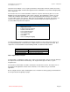
VC-55™ PR Voice Codec Board User’s Manual Version 1.3 Section 3 – Set-up & Control install: completed successfully Step 9 Next install the DSP inf file by typing the following: wdreg -inf c5509a.inf install the response will be install: completed successfully Step 10 Next install the software inf file type wdreg -inf vc55r10.inf install the response will be install: completed successfully Once the drivers and inf files are installed the VC-55™ Vocoder Board can be connected to the PC via USB.
VC-55™ PR Voice Codec Board User’s Manual Version 1.3 Section 3 – Set-up & Control Follow the instructions of the Upgrade Device Driver Wizard that opens. When asked, point to the location of the INF file in your distribution package. Once the drivers and inf files are installed the VC-55™ Vocoder Board can be connected to the PC via USB. To verify correct operation of the board run the VC-55™ Vocoder Board Program (vc55param.exe). Running the VC-55™ Vocoder Board Program vc55param.
VC-55™ PR Voice Codec Board User’s Manual Version 1.3 Section 3 – Set-up & Control quality audio output. -m -M Chan_Rx_Min_Time Chan_Rx_Max_Time Between 0-636 Jitter Buffer Minimum time This time is adjustable to compensate for jitter on the channel interface. The minimum buffer time can be set between 0 and 636 ms. The option is set by multpling the desired delay by 4000 (ex.
VC-55™ PR Voice Codec Board User’s Manual Version 1.3 Section 3 – Set-up & Control 4096 suppression (NS) and silence frame generation (DTX) in the encoder Enables Tone Detection.
VC-55™ PR Voice Codec Board User’s Manual Version 1.3 Encode_Mode Slip_Mode EncodeCmode Chan_Rx_Min_Time Chan_Rx_Max_Time Encode_Source Channel_Uart_Rate Sync_Err_Rate Lost_Sync_Rate Lost_Packets Dropped_Packets DecodeErrRate Section 3 – Set-up & Control board.
VC-55™ PR Voice Codec Board User’s Manual Version 1.
VC-55™ PR Voice Codec Board User’s Manual Version 1.3 Section 4 – Interface Protocol Channel Interface Digital Voice Systems, Inc. The Speech Compression Specialists Vocoder Board Channel Basic Operation All channel packets contain data (coded speech) that is sent to the decoder to synthesize speech. When a Channel packet is received the Vocoder Board decodes the packet and plays the synthesized speech out the selected analog interface.
VC-55™ PR Voice Codec Board User’s Manual Version 1.3 Section 4 – Interface Protocol rate Byte 1 is used to set the rate information of the data in the packet. The AMBE APCO PROJECT 25 coder runs in either one of two rates as shown in Table 9 Vocoder Rate .
VC-55™ PR Voice Codec Board User’s Manual Version 1.3 Section 6 – Support Specifications Digital Voice Systems, Inc. The Speech Compression Specialists Introduction This section contains hardware Specifications of the VC-55™ Vocoder Board. NOTE: All values are typical unless noted otherwise. All specifications subject to change.
VC-55™ PR Voice Codec Board User’s Manual Version 1.3 Section 6 – Support Line Out Type: Connector: Maximum Output Level Output Impedance: Bandwidth: A/D Resolution: SNR (Non-Weighted) A/D Sampling Rate: Minimum Load Single-ended Output female 3.5mm Audio Jack 1.0 Volt RMS <50 Ohms 20 Hz to 3.6 kHz (up to 48 kHz. available) 16 bits 84 dB 8 kHz (up to 96kHz.
VC-55™ PR Voice Codec Board User’s Manual Version 1.3 DC Power Input Voltage Input Current Section 6 – Support 5 Volts or 3.3 Volts DC 250 ma @ 5V / 3.3 VDC Mechanical Mechanical Weight Size (W X D X H) DVSI Confidential Proprietary 1.2 oz. (with connectors installed) 3.1875"X 2.
VC-55™ PR Voice Codec Board User’s Manual Version 1.3 Section 6 – Support Support Digital Voice Systems, Inc. The Speech Compression Specialists DVSI Technical Support If you have any problems with the VC-55™- PR Vocoder Board Voice Codec Board or have questions about its operation, please contact: Digital Voice Systems, Inc. 234 Littleton Road Westford, MA 01886 USA Phone: (978) 392-0002 Fax: (978) 392-8866 email: info@dvsinc.com web: www.dvsinc.
History of Revisions Revision Number Date of Revision Description Pages 1.1 February 2009 Removed Preliminary all 1.2 June 2011 Edited Description for LED 1 through LED 4 13 1.
NOTES DVSI Confidential Proprietary Page 22