
User`s manual


Page 45
DVSI Confidential Proprietary
USB-3000™
User’s Manual Version 1.6a
Section 4 - Data and Configuration Packets
Digital Voice Systems, Inc.
The Speech Compression Specialists
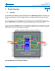
4.2. Packet Structure
he USB-3000™ transmits / receives data packets via the USB to the onboard FTDI USB chip. Then through
coder chip. The
t is recommended
Vocoder chip Users Manual to become familiar with the packet structure.
As the USB-30 acke oon as the
data is ready. The USB-3000™ sends response packets in the same order that the packets are received. The
AMBE-3000™ Vocoder Chip maintains a FIFO for received packets and a separate FIFO for packets that are
aw ion s h l ugh to to t p d two
channel packets. The USB-3000™ can continue to transmit/receive packets while it is still processing prior
pac
ke
When the USB-3000™ receives a speech packet, it takes the speech samples from the packet, encodes them
and sends back a channel packet.
l packet, it takes the channel data from the packet, decodes the
hannel data, and sends back a speech packet.
s
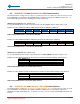
4.3. Example Product ID Packet
ill respond with a string that contains the product
T
the FTDI chip’s UART Serial interface packets are sent/received to/from the AMBE-3000™ vo
acket is the same structure as described in the AMBE-3000™ Vocoder chip Users Manual. Ip
that the user read the AMBE-3000™
00™ receives packets, it processes the packets and sends response p ts as s
aiting transmiss . The FIFO are eac arge eno accommodate up wo speech ackets an
ts.
When the USB-3000™ receives a channe
c
When the USB-3000™ receives a configuration control packet, it makes the requested configuration change
and sends back a configuration response packet.
The following are two simple examples of a configuration / control packet that can be used to gain a good
understanding of how the packet interface works.
When a Product ID packet is sent to the USB-3000™, it w
entification of the internal AMBE-3000™ Vocoder chip. id
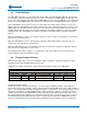
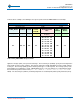
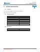
Following is an example configuration / control packet (hexadecimal) for input to the USB-3000™:
Packet Format with Parity Field
Control / Configuration Packet For PRODUCT ID
Packet Header Fields Parity
START_BYTE LENGTH TYPE Control Packet Field ID
PKT_PARITY PARITY_BYTE
(1 byte) (2 bytes) (1 byte) (1 byte) (1 byte) (1 byte)
61 0003 00 30 2F 1C
Table ROD
he first byte (0x61) is the packet header byte. The next two bytes (0x0003) specify the total length of the
re
ity byte for all received packets and discards any packet that has an incorrect parity byte.
2 PPKT_ ID Field
Product ID Packet Description
T
packet fields (3 bytes in this example). Note that the total packet length including the header, length, and type is
7 bytes. The next byte (0x00) specifies that the packet type is a control packet. The next byte (0x30) is the field
identifier for a indicating it is a PKT_PRODID request. The next two bytes (0x2F1C) show that parity fields a
enabled. The first byte of the parity field is the parity field identifier and is always equal to 0x2f. The second
byte of the parity field is the parity byte. It is obtained by “Exclusive-oring” every byte in the packet, except for
the START_BYTE and the PARITY_BYTE, together. If parity fields are enabled, the AMBE-3000™ Vocoder
hip checks the parC