
User`s manual
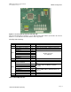

AMBE-3000™-HDK Development Board
User’s Manual
Version 1.1
2BHDK Configuration
Page 16
DVSI Confidential Proprietary
Vocoder Rate Selection
There are a three ways to configure the encoding/decoding rate for the AMBE-3000™ HDK. Hardware
switches (See Table 11 Board Dip Switches) allow the user to configure one of 64 standard rates. The
user is able to choose a rate through the PC interface when the HDK is attached to a PC via USB. The
user can recompile the AMBE-3000™ HDK source code to achieve any rate that they require.
After the HDK is reset, it resets the AMBE-3000™ Vocoder Chip. When the AMBE-3000™ Vocoder
Chip c
omes out of reset, the rate is selected via the configuration pins as shown in Table 12 AMBE-
3000™ Vocoder Chip UART Baud Rate Selection. The rate may be subsequently changed via software
by sending an appropriate packet to the AMBE-3000™ Vocoder Chip.
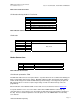
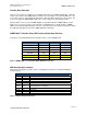
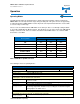
AMBE-3000™ Vocoder Chip UART Interface Baud Rate Selection
In all modes except A3KdirectMode the baud rate must be sent to 460,800 baud.
Baud Rate (baud) Position 7 Position 6 Position 5
28,800 ON ON ON
57,600 ON ON OFF
115,200 ON OFF ON
230,400 ON OFF OFF
460,800 OFF ON ON
921,600 OFF ON OFF
Table 12 AMBE-3000™ Vocoder Chip UART Baud Rate Selection
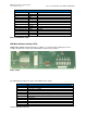
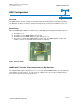
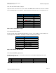
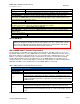
HDK Configuration Jumpers
Slide switches and jumpers provide control of configuration parameters for maximum flexibility of
vocoder features.
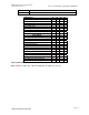
HDK Board Configuration Jumpers
Item Header Description
JP2 8x1 Enables AMBE-3000™ UART Rate Selection via Switch 2
JP4 8x1 Connects to AMBE-3000™ to set UART Rate
JP12 8x1 Enables AMBE-3000™ UART Rate Selection via µ-controller
JP11 8x2
Enables the HDK board status indicators LED’s to be
controlled by the µ-controller
JP13 2x1 Analog Audio I/O selection
JP16 2x1 Not Used
JP15 2x1 “WD Disable” Reserved
Table 13 Jumper Header Connectors