
User`s manual

AMBE-3000™-HDK Development Board
User’s Manual Version 1.1
Section 2 –
Page 12
DVSI Confidential Proprietary
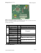
Connectors, Test Points & Indicators
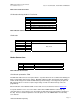
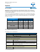
JP10 Header (MSP430 JTAG)
Pins Signal Signal Description
1 TDO/TDI
2 VCC
3 TDI/TCLK
5 TMS
6 NC
7 TCK
11 Resetn
4, 8, 9, 10, 12, 14 GND Ground
13 NC No Connection
Table 9 JP10 MSP430 JTAG
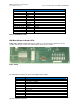
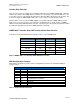
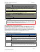
HDK Board Status Indicator LEDs
AMBE-3000™-HDK Development Board uses LEDs’ as a convenient way to display the current
condition of Audio I/O, vocoder and communications channel to the operator.
Figure 9 LEDs
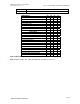
The LED indicators indicate the status of the HDK board as follows
LED ID # Description (when LED ON)
D1 Idle
D2 Low Power / Standby
D3 Reserved
D4 Reserved
D5 Indicates Encoder/Decoder Activity
D6 Reserved
D7 Reserved
D8 Reserved
D18 µ-controller power is active