
User`s manual
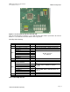

AMBE-3000™-HDK Development Board
User’s Manual Version 1.1
Section 2 –
Page 11
DVSI Confidential Proprietary
Connectors, Test Points & Indicators
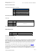
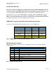
Table 5 JP5 Serial Test Points
JP7 Handset Analog Audio I/O Test Points
Handset I/O Test Points
Pin # Signal Description
1 Connected to Ground
2 Analog Out P1
3 Speaker Out
4 Microphone In/DC Microphone Bias out
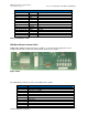
Table 6 Header I/O Test Points
JP8 Header
JP8 Header
Pins Signal Signal Description
1
5
2, 3, 4, 6, 7, 8
Not Used
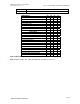
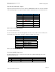
Table 7 JP8 Serial Data
Header Connections
HDK Board Header Connections
Item Header # of Pins Description
JP3 Header 7x2 Reserved
JP10 Header 7x2 JTAG Connection for the µ controller
Table 8 Header Connections
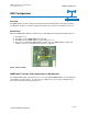
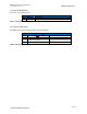
JP10 Header µController JTAG
The MSP430 JTAG connector is 2x7 pins with 0.1" step that follows the TI recommended JTAG layout.
PIN1 is marked with square pad on bottom. MSP430-JTAG has built-in target board voltage follower
and the JTAG voltage levels follow the MSP430 target board voltage, so the target may be powered
with voltage between 2.7 and 3.6 V (if the target voltage is under 2.7V Flash memory cannot be
programmed).
More information on the MSP430 JTAG can be found on Texas Instruments web site www.ti.com
Test points allow the user to access the data to and from the AMBE-3000™ Vocoder Chip. By
connecting to these test points the user can monitor the data flow and to understand the operation of
the chip. For more detailed explanation of the I/O signal, refer to the AMBE-3000™ Vocoder Chip
Users manual.