
User`s manual

AMBE-3000™-HDK Development Board
User’s Manual Version 1.1
Section 2 –
Page 10
DVSI Confidential Proprietary
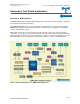
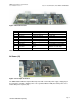
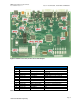
Connectors, Test Points & Indicators
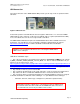
HDK Test Points
HDK Board Header Test Points
Item Header # of Pins Name Description
JP1 Header 8x1 LED Indicators HDK board status indicators
JP5 Header 2x1 Serial Data AMBE-3000™ Chip Serial I/O
JP7 ---- Handset IO N/A
JP8 Header 7x2 UART Output of the UART
Table 3 Header Test Points
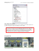
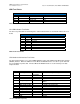
JP1 LED Indicators Test Points
The JP1 Test points allow for monitoring of the status indicator LED’s as described in Table 4 JP1 Test
Points
JP1 Header
Pin Signal Description
1 STAT7 Idle Indication
2 STAT6 Standby indication
3 STAT5 Reserved
4 STAT4 Reserved
5 STAT3 Run
6 STAT2 Reserved
7 STAT1 Reserved
8 STAT0 Reserved
Table 4 JP1 Test Points
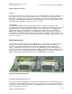
JP5 Header Serial Interface Test Points
The JP5 Header provides access to the AMBE-3000™ Vocoder chip’s Multichannel Buffered Serial Port
(McBSP) Interface. When the HDK is in Codec Mode the McBSP interface is used for speech data and
it is not available for packet data. In Packet Mode the McBSP interface is used for both speech data
and packet data.
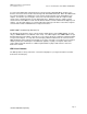
JP5 Header
Pins HDK Signal Name AMBE-3000™
Pin Number
AMBE-3000™ Signal Description
1 SER_CHAN_TxD 19 Serial Transmit Data Output
2 GND Ground
3 SER_CHAN_RxD 18 Serial Receive Data Input to the AMBE-
3000™
4 GND Ground
5 SER_CHAN_CLKR 21 Serial Receive Clock Input
6 SER_CHAN_CLKX 23 Serial Transmit Clock Output
7 GND Ground
8 SER_CHAN_FSR 24 Serial Receive Frame Input
9 SER_CHAN_FSX 22 Serial Transmit Frame Output
10 GND Ground
11 GND Ground
12 GND Ground