
User`s manual

AMBE-3000™-HDK Development Board
User’s Manual Version 1.1
Section 2 –
Page 8
DVSI Confidential Proprietary
Connectors, Test Points & Indicators
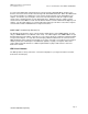
To connect two HDK boards together the device must be put into “Dual-HDK Mode” and P2 of one
board is connected to P2 of the other board using a RS-232 Null Modem Cable. When two HDK boards
are connected together to communicate, each converts the input analog speech into digital speech
samples, encodes the speech using the selected vocoder rate and then sends the compressed bit
stream out as serial data packets over the RS-232 interface. Simultaneously, the compressed bit
stream from the other HDK are read in from the RS-232 interface and decoded back into digital speech
samples. The decoded samples are converted back into analog speech via the codec whose output is
sent to both the handset and RCA line-level output connections.
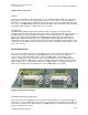
AMBE-3000™ Vocoder Chip RS-232 (P1)
The RS-232 Packet interface (P1) is connected to the UART interface of the AMBE-3000™ Vocoder
chip (see AMBE-3000™ User’s Manual section 2.5.2). The UART signals of the AMBE-3000™ are put
through a RS-232 receiver/driver so that the user can connect directly to a terminal or terminal emulator
on a personal computer. To set up this connection plug a RS-232 cable into the P1 connector on the
HDK and plug the other end into your terminal (or one of the serial ports on your PC if you are using an
emulator) and set the terminal up for 115,200 baud, eight bits, no parity, one stop bit, and no flow
control. When using this interface in “UART Loopback Mode” a jumper cable must be connected
between P1 and P2.
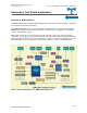
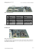
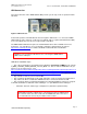
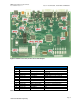
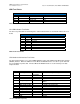
HDK List of Headers
The HDK provides a variety of Headers, connections and jumpers (see Figure 8 Header Test Points,
Connections and Jumpers).