
Specifications


AMBE-3000™ Vocoder Chip Users Manual
Version 2.8, August, 2011
I/
O Management
5.8 Interfacing a codec to the AMBE-3000™ Vocoder chip
5.8.1 The Texas Instruments General purpose TLV320AIC14
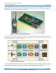
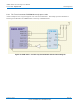
The Texas Instruments’ TLV320AIC14 codec presents a simple low cost solution for use with DVSI’s AMBE-3000™ vocoder
chip. This example provides information on interfacing theTLV320AIC14 to the AMBE-3000™ Vocoder chip SPI interface.
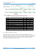
Figure 30 AMBE-3000™ Vocoder Chip and TLV320AIC14 Interface Block
Diagram
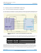
The control registers in the TLV320AIC14 codec must be initialized for proper operation. The recommended procedure is to
initialize the TLV320AIC14 by writing data to 5 control registers via packet from the AMBE-3000™ Vocoder Chip.
Control Register Configuration Data Notes:
1 0x41 set 16 bit DAC mode, set continuous data transfer mode
2 0xA0 set TURBO=1 (SCLK=MCLK/P), keep I2C addr=4
4 0x83 set M=3
5C 0xB8 sidetone=MUTE
6 0x02 set input MICIN self biased at 1.35 V
Table 27 Control Register Value for the TLV320AIC14
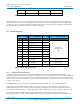
Various configuration data can be used to control the operation of the TLV320AIC14 codec (see its data sheet for more
information), however for reference the AMBE-3000™ Vocoder Chip has been tested with the TLV320AIC14 configured
using the register values shown in Table 27 Control Register Value for the TLV320AIC14. A reset to the TLV320AIC14
co
dec will reset all of the internal registers. As a result, the TLV320AIC14 must be reconfigured following a reset.
(Subject to Change) Page 49
DVSI CONFIDENTIAL PROPRIETARY