
Specifications


AMBE-3000™ Vocoder Chip Users Manual
Version 2.8, August, 2011
I/
O Management
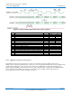
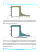
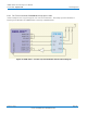
Figure 28 Front End Input Filter Mask
The voice coder interface requires the A-to-D and D-to-A converters to operate at an 8 kHz sampling rate (i.e. a sampling
period of 125 microseconds) at the digital input/output reference points. This requirement necessitates the use of analog filters
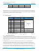
at both the input and output to eliminate any frequency components above the Nyquist frequency (4 kHz). The recommended
input filter mask is shown in Figure 28 Front End Input Filter Mask, and the recommended output filter mask is shown in
Figure 29 Front End Output Filter Mask. For proper operation, the shaded zone o
f the respective figure should bound the
frequency response of the front-end input and output.
Figure 29 Front End Output Filter Mask
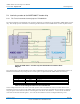
This document assumes that the A-to-D converter produces digital samples where the maximum digital input level (+3 dBm0)
is defined to be +/- 32767, and similarly, that the maximum digital output level of the D-to-A converter occurs at the same
digital level of +/- 32767. If a converter is used which does not meet these assumptions then the digital gain elements shown in
Figure 27 Vocoder Front End should be adjusted appropriately. Note that these ass
umptions are automatically satisfied if 16
bit linear A-to-D and D-to-A converters are used, in which case the digital gain elements should be set to unity gain.
An additional recommendation addresses the maximum noise level measured at the output reference points shown in Figure 27
Voc
oder Front End with the corresponding inputs set to ze
ro. DVSI recommends that the noise level for both directions should
not exceed -60 dBm0 with no corresponding input. In addition, the isolation from cross talk (or echo) from the output to the
input should exceed 45 dB which can be achieved via either passive (electrical and/or acoustic design) or active (echo
cancellation and/or suppression) means.
(Subject to Change) Page 48
DVSI CONFIDENTIAL PROPRIETARY