
Specifications

AMBE-3000™ Vocoder Chip Users Manual
Version 2.8, August, 2011
Electrical Characteristics and
Requirements
3.8.11 Additional Requirements when Low Power Mode is enabled.
If low power mode is enabled, there are some restrictions on when a packet can be sent to the AMBE-3000™ Vocoder Chip.
One of the following methods most be chosen.
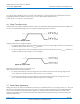
Method 1: Prior to the start of any packet transfer to the AMBE-3000™ Vocoder Chip, the STDBY_ENABLEn (TQFP pin 75
/ BGA pin K14) pin must be set low at least 500ns prior to sending the first byte of a packet via UART, McBSP, or Parallel
Port. The signal should be set high anytime after the first byte of the packet has been transferred to the AMBE-3000™
Vocoder Chip. When the STDBY_ENABLEn is held low, the AMBE-3000™ Vocoder Chip is prevented from entering the
standby state, so it is important that the STDBY_ENABLEn signal is set high prior to the end of the last byte of the packet.
OR
Method 2: STDBY_ENABLEn (TQFP pin 75 / BGA pin K14) must be pulled high or left disconnected. Prior to the start of
any packet transfer to the AMBE-3000™ Vocoder Chip, wait for a transition of the STANDBYn (TQFP pin 44 / BGA pin M6)
signal from the high state to the low state. After the transition is detected begin sending the first byte of the packet to the
AMBE-3000™ Vocoder Chip via UART, McBSP, or Parallel Port within 100µs after the transition was detected.
OR
Method 3: A packet may be sent to the AMBE-3000™ Vocoder Chip at anytime after the AMBE-3000™ Vocoder Chip has
begun transmitting a packet up until the time the AMBE-3000™ Vocoder Chip has just finished transmitting the packet. It is
important that the first byte of the packet being sent to the AMBE-3000™ Vocoder Chip be sent before the last byte of the
packet is received from the AMBE-3000™ Vocoder Chip.
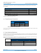
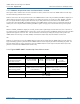
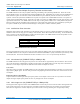
3.8.12 Typical AMBE-3000™ Vocoder Chip Power Measurements:
Test Conditions Power Measurement
Low Power Mode NOT Enabled Low Power Mode Enabled
Codec Mode (SPI Interface)
UART Packet Interface
50% Voice Activity
1.8v uses 162 mW
3.3v uses 10 mW
Total
172 mW
1.8v uses 74 mW
3.3v uses 9 mW
Total
83 mW
(DTX enabled)
Packet Mode
UART Packet Interface
Not receiving packets
129 mW
(AMBE-3000™ Vocoder Chip is
in the idle state)
3 mW
(AMBE-3000™ Vocoder Chip is in the
standby state)
Maximum Current Values
1.8v = 230 mW
3.3v = 125 mW
Table 8 Typical AMBE-3000™ Vocoder Chip Power Measurements
(Subject to Change) Page 26
DVSI CONFIDENTIAL PROPRIETARY