
Specifications

AMBE-3000™ Vocoder Chip Users Manual
Version 2.8, August, 2011
H
ardware Information
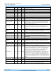
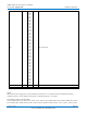
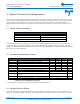
S_COM_RATE0 89 E13 Input LSB of Serial Communications Rate selection
S_COM_RATE1 90 E11 Input Serial Communications Rate selection
S_COM_RATE2 91 F10 Input MSB of Serial Communications Rate selection
SPI_WAKE 106 D9 Input
Must be connected to the active low frame sync signal from the
codec if the SPI interface is used and low power mode is enabled.
The signal is used to wake the AMBE-3000™ Vocoder Chip from
stand-by mode.
UART_TX 111 C7 Output
Channel Transmit Data from AMBE-3000™ Vocoder Chip SCI
asynchronous serial port. This pin must be held HIGH during a
Hard Reset.
UART_RX 112 A7 Input
Channel Receive Data to AMBE-3000™ Vocoder Chip
asynchronous serial port.
RESETn 113 D6 Input AMBE-3000™ Vocoder Chip Reset pin. Active LOW
ES_ENABLE 119 B5 Input Echo Suppressor enable / disable
EC_ENABLE 120 D5 Input Echo Canceller enable / disable
RATE5 121 E5 Input Vocoder Bit Rate Control Word
RATE4 122 A4 Input Vocoder Bit Rate Control Word
RATE3 123 B4 Input Vocoder Bit Rate Control Word
RATE2 124 C4 Input Vocoder Bit Rate Control Word
RATE1 125 D4 Input Vocoder Bit Rate Control Word
RATE0 126 A3 Input Vocoder Bit Rate Control Word
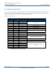
1v8
20, 29,
42, 56,
63, 74,
82, 94,
102,
110,
114
B10,
C8,
C14,
G12,
H1,
K12,
L1,
P5,
P9,
P12,
A6
PWR Supply Voltage 1.8-V Core Digital Power Pins. (V
DD
)
3v3
1, 13,
14, 25,
49, 83,
104,
118
B2,
E1,
F4,
E9,
G11,
J4,
L7,
A5,
L10,
N14,
PWR 3.3 V I/O Digital Power Pins.
(Subject to Change) Page 13
DVSI CONFIDENTIAL PROPRIETARY