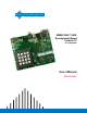
Digital Voice Systems, Inc. The Speech Compression Specialists AMBE-20x0™-HDK Development Board Version 2.
AMBE-20x0™-HDK Development Board User’s Manual Version 2.3 07, September Copyright, 2007 Digital Voice Systems, Inc 234 Littleton Road Westford, MA 01886 This document may not, in whole or in part be copied, photocopied, reproduced, translated, or reduced to any electronic medium or machine readable form without prior consent in writing from Digital Voice Systems, Incorporated. Every effort has been made to ensure the accuracy of this manual. However, Digital Voice Systems, Inc.
AMBE-20X0™-HDK Development Board User’s Manual (Preliminary) Information – Section AMBE-20x0™-HDK Development Board END USER License Agreement *** Important Read Carefully *** This end user license agreement is a legal agreement between the customer (the END USER) and Digital Voice Systems, Inc. (DVSI) covering the terms and conditions under which DVSI's proprietary software, documentation and other material which may be provided with the AMBE-20x0™-HDK Development Board is licensed to the END USER. 1.
AMBE-20X0™-HDK Development Board User’s Manual (Preliminary) Information – Section Special Handling Instructions To avoid damage from the accumulation of a static charge, industry standard electrostatic discharge precautions and procedures must be employed during handling and installation the AMBE-20x0™-HDK Development Board. Read Instructions and Users Manual – All of the safe handling and operating instructions should be read before integration of the AMBE-20x0™-HDK Development Board begins.
AMBE-20X0™-HDK Development Board User’s Manual (Preliminary) Section – Table of Contents Table of Contents Preliminary Section 1 INTRODUCTION ....................................................................1 GENERAL INFORMATION .........................................................................................1 OVERVIEW ............................................................................................................2 AMBE-2000™ INSIDE .................................................
AMBE-20X0™-HDK Development Board User’s Manual (Preliminary) Section – Table of Contents BOARD CONNECTIONS ........................................................................................ 28 AUDIO I/O CONNECTIONS .................................................................................... 28 HEADER CONNECTIONS....................................................................................... 30 ELECTRICAL INPUT ...........................................................................
AMBE-20X0™-HDK Development Board User’s Manual (Preliminary) Section – Table of Contents FIGURE 3 POWER INPUT CONNECTION....................................................................................7 FIGURE 4 CONSOLETERMINAL SETTINGS ................................................................................9 FIGURE 5 CONNECTING TWO HDK BOARDS TOGETHER ..........................................................9 FIGURE 6 PHOTO OF JTAG CONNECTIONS .................................................
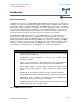
AMBE-20x0™-HDK Development Board User’s Manual (Preliminary) Section 1 – Introduction Introduction Digital Voice Systems, Inc. The Speech Compression Specialists General Information The Digital Voice Systems, Inc. (DVSI) AMBE-20x0™-HDK Development Board is an comprehensive, evaluation, test and development platform that helps product designers and manufacturing engineers TM gain experience with the low-bit-rate AMBE-2000 and AMBE-2020™ Vocoder Chips.
AMBE-20x0™-HDK Development Board User’s Manual (Preliminary) Section 1 – Introduction Overview The AMBE-20x0™ Hardware Development Kit (HDK) is designed to streamline the development of products engineered around the AMBE-2000™ Vocoder chip. The AMBE- 20x0™ HDK is a completely functional system from the analog audio interface to the digital channel interface.
AMBE-20x0™-HDK Development Board User’s Manual (Preliminary) Section 1 – Introduction Figure 1 basic block diagram of the AMBE-2000 HDK board The AMBE-2000™ has a master clock frequency of 16.384 MHz delivered via a surface mount crystal. AMBE-2000™ inside The AMBE-2000™ Vocoder Chip provides a real-time, full-duplex implementation of DVSI's standardsetting Advanced Multi-Band Excitation AMBE® voice compression technology.
AMBE-20x0™-HDK Development Board User’s Manual (Preliminary) Section 1 – Introduction AMBE-2000™ Vocoder Chip Applications AMBE-2000™ Vocoder Chip Applications Cellular Telephony and PCS Satellite Communications Digital Mobile Radio Secure Communications Voice Multiplexing Voice Mail Multimedia Applications Video Conferencing Documentation Table 2 AMBE-2000™ Applications Data Rates from 2000bps to 9600bps The total coded bit rate is the sum of two components, the Speech Data bit rate and the Forward Erro
AMBE-20x0™-HDK Development Board User’s Manual (Preliminary) Section 1 – Introduction Voice Activation Detection (VAD) The Voice Activation Detection (VAD) algorithm along with the Comfort Noise Insertion (CNI) feature of the AMBE-2000™ chip performs useful functions in systems trying to convert periods of silence, that exist in normal conversation, to savings in system bandwidth or power. . For more information regarding the VAD, refer to the AMBE-2000 User’s Manual.
AMBE-2x0™-HDK Development Board User’s Manual (Preliminary) Section 2 – Connectors, Test Points & Indicators Connectors, Test Points & Indicators Digital Voice Systems, Inc. The Speech Compression Specialists Overview As a standalone development tool, the AMBE-2000™-HDK can process analog audio input and send the synthesized speech to the analog audio outputs. Alternatively, the RS-232 channel interface can be connected to a PC for processing files.
AMBE-2x0™-HDK Development Board User’s Manual (Preliminary) Section 2 – Connectors, Test Points & Indicators DC Power The AMBE-20x0™-HDK Development Board operates with a 5.0 V DC power supply. Simply plug in the 120 V AC to 5.0 V DC (~250ma) power source (provided in the HKD Kit) into the DC power receptacle (See photo in Figure 3 Power Input Connection). + 5.
AMBE-2x0™-HDK Development Board User’s Manual (Preliminary) Section 2 – Connectors, Test Points & Indicators Handset If a handset is used instead of the 4 wire interface, use a standard telephone handset (included in the optional accessories kit) to connect to the RJ11 handset connector. Be sure that the handset cord is less than a foot long (included in the optional accessories kit) when not stretched. This will help reduce noise from being introduced into the voice signal.
AMBE-2x0™-HDK Development Board User’s Manual (Preliminary) Section 2 – Connectors, Test Points & Indicators Figure 4 ConsoleTerminal Settings Channel I/O The channel connection on the HDK Board is an asynchronous RS-232 interface for connecting directly to a serial device or another HDK Board.
AMBE-2x0™-HDK Development Board User’s Manual (Preliminary) Section 2 – Connectors, Test Points & Indicators Console Out The bottom serial port on the HDK provides a simple ASCII text output intended for monitoring the current configuration and operation of the board. A terminal or terminal emulator on a personal computer may be used to connect the interface.
AMBE-2x0™-HDK Development Board User’s Manual (Preliminary) Section 2 – Connectors, Test Points & Indicators XC9572 JTAG MSP430 JTAG Figure 6 Photo of JTAG Connections PLD JTAG Interface JTAG operation for the XC9572XL consists of four signals: TMS, TDI, TDO, and TCK. These signals interact with the device through the TAP Controller, a 16-state finite state machine. The JTAG TMS signal controls transitions between states.
AMBE-2x0™-HDK Development Board User’s Manual (Preliminary) Section 2 – Connectors, Test Points & Indicators AMBE-2000™ Pins 1 2 3 4 5 6 7 8 9 10 11 12 JP1 Header Signal GND GND AMBE Channel Data OUT AMBE Channel TX Strobe Channel Clock AMBE output PCM Codec TX/RX Strobe /BCK AMBE input PCM AMBE Channel Data IN GND GND Pins 1 2 JP2 header Signal Analog Out (RCA) GND Table 8 AMBE-2000 Test Points Analog I/O Table 9 Analog Test Points (JP2) Pins 1 2 3 4 JP3 Header Signal GND GND Analog OUT (Handset)
AMBE-2x0™-HDK Development Board User’s Manual (Preliminary) Section 2 – Connectors, Test Points & Indicators HDK Board Status Indicator LEDs AMBE-20x0™-HDK Development Board uses LEDs’ as a convenient way to display the current condition of Audio I/O, vocoder and communications channel to the operator.
AMBE-20x0™-HDK Development Board User’s Manual (Preliminary) Section 3 – HDKConfiguration & Data Rate Selection HDK Configuration & Data Rate Selection Digital Voice Systems, Inc. The Speech Compression Specialists Overview The AMBE-2000™ Vocoder settings are determined by both the DIPswitch and Jumper positions. The Dipswitch positions are always read upon board power up or after a the Reset Button is pressed.
AMBE-20x0™-HDK Development Board User’s Manual (Preliminary) Section 3 – HDKConfiguration & Data Rate Selection Jumper JP5 SW1 SW2 Figure 8 Vocoder Settings Switches SW1 and SW2 Slide Dip-Switch Settings Switch SW1 and SW2 Description Down Position Up Position D1-1 D1-2 See Table Table 14 Standard Rate Table D1-3 for AMBE-20x0 D1-4 D1-5 D1-6 See Table Table 15 Channel Interface Selection Table D2-1 D2-2 Active Inactive D2-3 Inactive Active See Table Table 16 Unframed Bit per D2-4 Word Selection Table D2
AMBE-20x0™-HDK Development Board User’s Manual (Preliminary) Total Rate (bps) 2000 2400 3600 3600 4000 4000 4800 4800 6400 6400 7200 7200 8000 8000 9600 9600 Speech Rate (bps) 2000 2400 2350 3600 3350 3600 4000 3750 4000 2400 4800 4550 3600 3100 4800 4000 3600 2400 4150 6400 4000 4400 4400 7750 4650 8000 4000 9600 4850 9600 3600 2400 Section 3 – HDKConfiguration & Data Rate Selection FEC Rate (bps) 0 0 50 0 250 0 0 250 0 1600 0 250 1200 1700 0 800 1200 2400 2250 0 2400 2800 2800 250 3350 0 4000 0 4750
AMBE-20x0™-HDK Development Board User’s Manual (Preliminary) Section 3 – HDKConfiguration & Data Rate Selection Number of voice data bits per word Switch 2 Position 4 BAUD_SEL1 (AMBE-2000™ pin 81) 1 Down 2 Down 3 Up 4 Up Switch 2 Position 5 BAUD_SEL0 (AMBE-2000™ pin 80) Down Up Down Up Table 16 Unframed Bit per Word Selection Table Jumpers JP5 Pins Jumper on Pin 1 Jumper on Pin 3 Signal VAD EN VAD Disable Table 17 Jumper Settings HDK RS-232 Interface Set-up via Keypad HDK board RS-232 channel Interf
AMBE-20x0™-HDK Development Board User’s Manual (Preliminary) Section 4 – Communication via Channel Interface Communication via Channel Interface Digital Voice Systems, Inc. The Speech Compression Specialists Overview AMBE-20x0™-HDK board has two RS-232 connections that provide communication to and from the board. The top connector is the RS-232 channel interface that provides the compressed voice serial data bit stream.
AMBE-20x0™-HDK Development Board User’s Manual (Preliminary) Section 4 – Communication via Channel Interface When power is applied to the board, the HDK sets the configuration of the AMBE-2000 vocoder chip to the setting as set by the dipswitches. This allows to the board to keep the configuration setting in between power cycling or after pressing reset.
AMBE-20x0™-HDK Development Board User’s Manual (Preliminary) Compressed Voice Bit Rate Section 4 – Communication via Channel Interface Compressed voice Number of data bits 2000 2400 3000 3600 4000 4200 4400 4800 7200 8000 9600 40 48 60 72 80 84 88 96 144 160 192 Total Packet Length (Number of channel data words including sync word) 4 4 5 6 6 7 7 7 10 11 13 Table 19 Example Packet Size for Various Compresssed Voice Data Rates Data Structure “AMBE-2000 Format” Packet The data structure in AMBE-2000 fo
AMBE-20x0™-HDK Development Board User’s Manual (Preliminary) Section 4 – Communication via Channel Interface HDK Audio Codec Loop Back The AMBE-2000™ HDK can run in a standalone nature. The audio interface is able to be looped back so that the input audio (from the handset or line in) goes through the codec only and the result is heard at the output. To loopback only through the codec remove the Jumper on JP6. Then input audio will go through the AD/DA process and output the handset and line out.
AMBE-20x0™-HDK Development Board User’s Manual (Preliminary) Section 4 – Communication via Channel Interface Connecting two Boards together via RS-232 Channel I/O The AMBE-2000™ HDK can be directly connected to a second AMBE-2000™ HDK via the channel interface creating a full duplex channel between the two boards. When connected, the analog voice from the first AMBE-20x0™-HDK Development Board is encoded and sent across the RS-232 channel interface.
AMBE-20x0™-HDK Development Board User’s Manual (Preliminary) Section 4 – Communication via Channel Interface Connecting the Console Out UART Serial Connection to a PC The bottom RS-232 port connector outputs information for monitoring the configuration and state of the AMBE-20x0™-HDK Vocoder board to console or a PC. For Console Out interface settings refer to Table 5 Console Out UART Serial Port Settings page 10.
AMBE-20x0™-HDK Development Board User’s Manual (Preliminary) Line 1 Display Item RS-232 Baud Rate Selection Page 2 Current Baud Rate = XX 3 Minimum Baud Rate = XX 4 Press 0-4: For Baud Rates 4800, 7200, 9600, 14400, 19200 respectively 5 Press 5-9: For Baud Rates 28800, 38400, 57600, 76800 115200 respectively 6 Press Digit to Select Rate, then Press * to Exit 7 Autobaud will be turned off Section 4 – Communication via Channel Interface Description Menu title Current rate as shown in line 4 an
AMBE-20x0™-HDK Development Board User’s Manual (Preliminary) Section 4 – Communication via Channel Interface After making a selection press “*” and the board will print to screen new HDK board current settings.
AMBE-20x0™-HDK Development Board User’s Manual (Preliminary) Section 4 – Communication via Channel Interface Running the ambe_hdk.exe file To record and playback encoded file the HDK must be running in AMBE-2000 packet format and dip switched SW1 and SW2 must be set as shown in Table 20 Dip Switch Settings for File I/O. Also, the VAD must be enabled (Jumper JP5 set between Pin 1 and Pin 2). To put the HDK into AMBE-2000 Packet format refer to Error! Reference source not found. Section.
AMBE-20x0™-HDK Development Board User’s Manual (Preliminary) Section 4 – Communication via Channel Interface Then enter the letter (“a” thru “h” or “x”) that corresponds to the serial port you are connected to and press ENTER The program will respond with Port = COM1 (the com port you selected) Mode = Record (Indicating record mode) Record File = abc_voice.
AMBE-20x0™-HDK Development Board User’s Manual (Preliminary) Section 5 – Specifications Specifications Digital Voice Systems, Inc. Overview The Speech Compression Specialists This section contains hardware Specifications of the AMBE-20x0™-HDK Development Board. NOTE: All specifications subject to change.
AMBE-20x0™-HDK Development Board User’s Manual (Preliminary) Section 5 – Specifications available) D/A Resolution 16 bits D/A Sampling Rate: 8 kHz (up to 96kHz. available) SNR (Non-Weighted) 81 dB Note: A 1.414 V signal on the line input produces digital max when the codec input gain is 0 dB. Line Out Type: Connector: Maximum Output Level Output Impedance: Bandwidth: A/D Resolution: SNR (Non-Weighted) A/D Sampling Rate: Minimum Load Single-ended Output female 3.5mm Audio Jack 1.
AMBE-20x0™-HDK Development Board User’s Manual (Preliminary) Section 5 – Specifications Header Connections J15 DSP JTAG Pin Number Name 1 TMS 2 TRSTn 3 TDI 4 Digital Ground 5 Sys_3v3 6 7 TDO Pin Number 8 9 10 11 12 13 14 Name Digital Ground TCK Digital Ground TCK Digital Ground EMU0 EMU1 Electrical Input J10 Power Pin Number Center Shield Name +5 Volts DC Ground DC Power Input Voltage Input Current 5 Volts DC 250 ma @ 5V DC Mechanical Mechanical Weight Size (W X D X H) 5.3 oz.
AMBE-20x0™-HDK Development Board User’s Manual (Preliminary) Section 6 – Additional Resources Additional Resources Third Party Tools Digital Voice Systems, Inc. The Speech Compression Specialists MSP-430 Flash Programmer Part Number: MSP-PRGS430 http://focus.ti.com/docs/toolsw/folders/print/msp-prgs430.html Xilinx Platform Cable USB Part Number: DLC9 http://www.xilinx.com/xlnx/xebiz/designResources/ip_product_details.jsp?key=HWUSB&iLanguageID=1 MSPGCC MSP-430 GNU Compiler http://mspgcc.sourceforge.
AMBE-20x0™-HDK Development Board User’s Manual (Preliminary) Section 6 – Introduction MSP430 Input/Output Pin Description MSP430 Input/Output Pin Description Pin No. 12 13 14 15 16 27 18 19 20 21 22 23 24 25 26 27 28 29 30 31 32 33 34 35 I/O Port Bank Port No.
AMBE-20x0™-HDK Development Board User’s Manual (Preliminary) 13 14 15 16 17 18 19 20 21 22 23 24 25 26 27 28 29 30 31 32 33 34 35 36 37 38 39 40 41 42 43 44 Section 6 – Introduction I O O O O O O O O JTAG O O I O O I I I O I O O I/O I I I O TX_DATA_0 RX_DATA_7 VCC RX_DATA_6 GND RX_DATA_5 RX_DATA_4 RX_DATA_3 RX_DATA_2 RX_DATA_1 RX_DATA_0 TDO GND VCC RX_FULL TX_EMPTY AMBE_CHAN_DX AMBE_CHAN_DR AMBE_CHAN_FS SHIFT_RX *POWER_ON_RESET MSP430_RESET VCC CHAN_CLK SHIFT_TX DIGIT_0 DIGIT_1 N/C LED_EN LED_CTL BCK_BU
AMBE-20x0™-HDK Development Board User’s Manual (Preliminary) Section 6 – Introduction Application Information It is strongly recommended that the user review the Application Information provided in the Texas Instruments PCM3500 data sheet before finalizing any design. Additional Reference Material AMBE-2000™ or AMBE-2020™ vocoder chip Users Manual http://www.dvsinc.com/literature.htm Application Report – Understanding Data Converters: http://www-s.ti.com/sc/psheets/slaa013/slaa013.
AMBE-20x0™-HDK Development Board User’s Manual (Preliminary) Section 7 – Support Support Digital Voice Systems, Inc. The Speech Compression Specialists DVSI Contact Information If you have problems or questions about the AMBE-20x0™-HDK Development Board please contact: Digital Voice Systems, Inc. 234 Littleton Road Westford, MA 01886 USA Phone: (978) 392-0002 Fax: (978) 392-8866 email: info@dvsinc.com web: www.dvsinc.
Section 7 – Support AMBE-20x0™-HDK Development Board User’s Manual (Preliminary) History of Revisions Revision Number Date of Revision 1 8-25-06 2 12-06-06 3 1-3-07 4 7-9-07 5 9-19-07 Description Page Edits to Serial, MSP430, and Xilinx Schematics Added RS-232 cable Pin out drawings Fig. 10 and Fig.
AMBE-20x0™-HDK Development Board User’s Manual (Preliminary) DVSI Confidential Proprietary Section 7 – Support Page 46