
User`s manual

AMBE-2000™ Vocoder Chip
User’s Manual Version 4.9
DVSI Confidential Proprietary, Subject to Change Page 9
Visit us at www.dvsinc.com
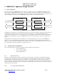
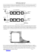
In order to ensure proper performance from the voice coder, it is necessary for the vocoder front end to meet a set of minimum
performance requirements. For the purposes of this section the vocoder front end is considered to be the total combined
response between microphone/speaker and the digital PCM interface to the vocoder, as shown in Figure 2-B. This includes any
analog electronics plus the A-to-D and D-to-A converters as well as any digital filtering performed prior to the voice encoder
or after the voice decoder.
Analog
Input
Gain
Analog
Input
Filter
A-to-D
Convertor
Microphone
Speaker
Analog
Output
Gain
Analog
Output
Filter
D-to-A
Convertor
AMBE+™
Voice
Encoder
AMBE+™
Voice
Decoder
Analog Input
Reference Pt.
Analog Output
Reference Pt.
Digital Output
Reference Pt.
Digital Input
Reference Pt.
Analog Speech
Digital Speech
(8 kHz sampling)
Digital
Input
Gain
Digital
Output
Gain
Vocoder Front End
Figure 2 - B. Vocoder Front End
The AMBE+™ voice encoder and decoder operate with unity (i.e. 0 dB) gain. Consequently the analog input and output gain
elements shown in Figure 2 are only used to match the sensitivity of the microphone and speaker with the A-to-D converters
and D-to-A converters, respectively. It is recommended that the analog input gain be set such that the RMS speech level under
nominal input conditions is 25 dB below the saturation point of the A-to-D converter (+3 dBm0). This level, which equates to
-22 dBm0, is designed to provide sufficient margin to prevent the peaks of the speech waveform from being clipped by the A-
to-D converter.
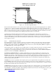
+2 dB
0 200 3400 4000
-1 dB
4600
freq (Hz)
-2 dB
3000
-40 dB
-35 dB
-18 dB
8000400
Figure 2 - C. Front End Input Filter Mask
The voice coder interface requires the A-to-D and D-to-A converters to operate at an 8 kHz sampling rate (i.e. a sampling
period of 125 microseconds) at the digital input/output reference points. This requirement necessitates the use of analog filters
at both the input and output to eliminate any frequency components above the Nyquist frequency (4 kHz). The recommended
input filter mask is shown in Figure 2 - C, and the recommended output filter mask is shown in Figure 2 - D. For proper
operation, the shaded zone of the respective figure should bound the frequency response of the front-end input and output.