
User`s manual

AMBE-2000™ Vocoder Chip
User’s Manual Version 4.9
DVSI Confidential Proprietary, Subject to Change Page 57
Visit us at www.dvsinc.com
8.4 Interfacing to the Texas Instruments PCM3500 Codec
The Texas Instruments PCM3500 codec chip presents a simple low cost solution for use with DVSI’s AMBE-2000™ or
AMBE-2020™ vocoder chips. This application note provides information on alternative methods of interfacing these
components.
PCM3500
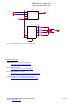
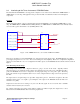
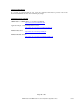
The block diagram in Figure 1 shows a sample interface between the PCM3500 codec and DVSI’s AMBE-2000™ vocoder
chip. The AMBE-2000™ or AMBE-2020™ CODEC_SEL bits (see AMBE-2000™ or AMBE-2020™ users manual) must be
set for use with a generic 16 bit linear codec (CODEC_SEL1,0 – 00).
3.3V
Master/Slave
U1
AMBE
-2000
27
33
37
29
31
41
CODEC_RX_CLCK
CODEC_TX_CLCK
CODEC_TX_STRB
CODEC_RX_STRB
CODEC_RX_DATA
CODEC_TX_DATA
U2
PCM3500
8
9
11
10
6
13
24
/BCK
FS
DOUT
DIN
M/S
Vdd
Vcc
Figure 1: The AMBE-2000™ Vocoder with the PCM3500 CODEC
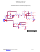
There are two advantages to using the PCM3500 codec. The first is the single supply design. The PCM3500 supports a single
power supply design from +2.7 v to +3.6 v. The second advantage lies in its simplicity. There are no complicated configuration
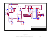
schemes associated with the codec. For configuration information, please see the PCM3500 data sheet and the reference circuit in
Figure 2.
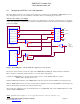
Notes On Analog Circuit Design
The example circuit assumes that a telephone handset is going to be used in the circuit. Typically, handset
microphones have a very small gain and the output is at moderately low levels (on the order of 50 millivolts peak to
peak). The PCM3500 Voice Codec is designed for an analog input voltage of 2 volts peak to peak. The analog
input in the reference design is amplified (Gain = 22) in order to bring the handset voltage to the level expected by
the ADC.
The output section is designed using a low pass filter design with a gain of 1. The filter is designed to allow the
maximum amount of the voice signal to pass unimpeded. The output of the PCM3500 should be filtered for
maximum voice quality.
Capacitors C13 and C14 are for creating a very low noise DC bias signal. If a low noise DC bias is available
elsewhere in the circuit, they are not needed.
For optimum performance, the analog circuit should be adjusted for whatever input (and output) device is used.
Please reference the PCM3500 data sheet for the analog requirements.