
User`s manual

AMBE-2000™ Vocoder Chip
User’s Manual Version 4.9
DVSI Confidential Proprietary, Subject to Change Page 50
Visit us at www.dvsinc.com
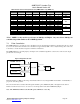
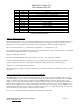
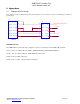
8.2 Example: Texas Instruments TLV320AIC10 Usage
The Texas Instruments’ TLV320AIC10 codec presents a simple low cost solution for use with DVSI’s AMBE-2000™
vocoder chip. This application note provides information on interfacing these components. Figure 1 shows a sample block
diagram interface, between the TLV320AIC10 codec and DVSI’s AMBE-2000™ vocoder chip.
SERIAL
DATA
VOICE_*RESET
VDD
SCLK
VDD
16.384 MHz
CODEC Configuration
*SEE DETAIL
BELOW
AMBE-2000
AVDD
U27
TLV320AIC10
13
16
17
26
3
2
1
45
34
33
40
42
46
25
7
6
5
4
15
30
14
29
24
38
23
22
21
48
47
10
11
20
27
9
8
12
19
43
*RESET
DOUT
DIN
ALTIN
AURXCP
AURXM
AURXFP
AVDD1
AVDD2
AVSS
AVSS
AVSS
AVSS
DCSI
DTXIM
DTXIP
DTXOM
DTXOP
DVDD1
DVDD2
DVSS
DVSS
FC
FILT
FLAG
FS
FSD
INM
INP
M0
M1
MCLK
M/*S
OUTM
OUTP
*PWRDWN
SCLK
VMID
U1
41
33
27
29
37
31
CODEC_TX_DATA
CODEC_TX_CLK
CODEC_RX_CLK
CODEC_RX_STRB
CODEC_TX_STRB
CODEC_RX_DATA
VDD
Figure 1: AMBE-2000™ and TLV320AIC10 sample block diagram
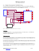
Configuration:
To configure the AMBE-2000™ for operation with the TLV320AIC10, set the CODEC_SEL pins on the AMBE-2000™
vocoder chip to work with a generic 16 bit linear 8 kHz codec as follows:
CODEC_SEL [1-0] (pins 85,84) = 00b
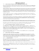
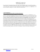
Initialization Procedure:
The control registers in the TLV320AIC10 codec must be initialized for proper operation. The recommended procedure is to
initialize the TLV320AIC10 by writing data to its 4 control registers through the DCSI port, while the AMBE-2000™ is held
in reset. The timing for the DCSI port is shown in Figure 2.
Note that the Device Address (D14-D12) is normally set to 0 unless multiple codec devices are used in cascade. Be sure that
the stop bit is at least 2 clock pulses long between data words as shown in the timing diagram. Shift the control words into the
device 1 bit at a time at the rate of SCLK.
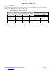
Various configuration data can be used to control the operation of the TLV320AIC10 codec (see the data sheet for more
information), however for reference the AMBE-2000™ has been tested with the TLV320AIC10 configured using the register
values shown in Table 1. Once the TLV320AIC10 is configured, the AMBE-2000™ should be taken out of reset to begin
communication with the codec.