
User`s manual

AMBE-2000™ Vocoder Chip
User’s Manual Version 4.9
DVSI Confidential Proprietary, Subject to Change Page 42
Visit us at www.dvsinc.com
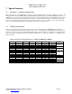
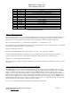
Table 7-B Rate Selection Using Rate Info 0-4, AMBE-2000™ only (AMBE+™)*
RATE_SEL4
Pin
RATE_SEL3
Pin
RATE_SEL2
Pin
RATE_SEL1
Pin
RATE_SEL0
Pin
Speech Rate
(bps)
FEC Rate (bps)
Total Rate
(bps)
1 1 1 1 1 2000* 0 2000
1 0 0 0 0 3600 0 3600
1 0 0 0 1 4000 0
1 0 1 1 0 2400 1600
4000
1 0 0 1 0 4800 0
1 1 0 0 0 4000 800
1 0 1 1 1 3600 1200
1 1 0 0 1 2400 2400
4800
1 0 0 1 1 6400 0
1 1 0 1 0 4000 2400
6400
1 1 0 1 1 4400 2800 7200
1 0 1 0 0 8000 0
1 1 1 0 0 4000 4000
8000
1 0 1 0 1 9600 0
1 1 1 0 1 3600 6000
1 1 1 1 0 2400 7200
9600
*Note: AMBE+ is only used for speech rates at 3600 bps and higher. Any rates below 3600 bps use
a modified algorithm similar to the AMBE algorithm.
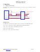
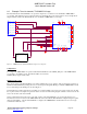
7.3 Echo Cancellation
The AMBE-2000™ Vocoder Chip provides a 16-millisecond echo canceller that is suitable for canceling the local echo caused
by a 2-to-4 wire hybrid and can achieve echo cancellation of approximately 30dB or more. Only the linear portion of the echo
is cancelled, so circuits should be designed to minimize non-linearities.
The AMBE-2000™ Vocoder Chip employs an adaptive echo cancellation algorithm to cancel echoes of the decoder output
present at the encoder input.
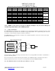
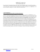
Figure 7-A Typical Echo Path
AMBE-2000
Decoder
8kHz Speech Data
Encoder
8kHz Speech Data
A/D-D/A
4 to 2 wire
Converter
Echo Path A
Echo Path B
The Echo Return Loss (ERL) of the analog circuit must be 6dB or more (in diagram ERL = Echo Path A – Echo Path B) for
proper echo canceller operation.
The echo canceller can be activated either through the hardware pin 78, ECHOCAN_EN, or through the Control Word
interface described in section 5.2.9. See section 7.1 for an important note about the ECHOCAN_EN pin.
Note: The AMBE-2000™ Echo Canceller will operate with linear codecs only.