
User`s manual

AMBE-2000™ Vocoder Chip
User’s Manual Version 4.9
DVSI Confidential Proprietary, Subject to Change Page 4
Visit us at www.dvsinc.com
1.
Product Introduction 6
1.1
General Information 6
1.2
Advantages 6
1.3
Typical Applications 7
2.
AMBE-2000™ Application Design Overview 8
2.1
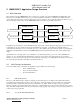
Basic Operation 8
2.2
Initial Design Considerations 8
2.2.1
A/D – D/A Overview 8
2.2.2
Vocoder Front End Requirements 8
2.2.3
Channel Interface Overview 10
2.2.4
Speech and FEC Rate Selection Overview 11
3
Hardware Information 12
3.1
Special Handling Instructions 12
3.1.1
Storage 12
3.2
Pin Descriptions 13
3.3
Clock and Reset Timing 15
3.4
Associated Chip Delay 17
3.5
Crystal / Oscillator Usage 17
3.5.1
TTL Clock Source 17
3.5.2
Crystal Oscillator 17
3.6
Package Description 19
3.7
Normal Operating Conditions 20
3.8
Absolute Maximum Ratings 20
3.9
Electrical Characteristics and Requirements 21
3.10
Thermal Resistance Characteristics 21
4
Channel Interface 22
4.1
Overview 22
4.2
Serial Configuration Selection 23
4.3
Channel Serial Mode 24
4.3.1
Low Level Timing for Passive and Active Serial Mode 25
5
Channel Data Format 27
5.1
Framed Format 27
5.2
Framed Input 27
5.2.1
Framed Input: Word 0 : Header 28
5.2.2
Framed Input: Word 1 : Power Control ID 28
5.2.3
Framed Input: Word 1 : Control Word 1 28
5.2.4
Framed Input: Words 2-6 : Rate Information 28
5.2.5
Framed Input: Word 7 : Unused in Input 29
5.2.6
Framed Input: Word 8 : Unused in Input 29