
User`s manual

AMBE-2000™ Vocoder Chip
User’s Manual Version 4.9
DVSI Confidential Proprietary, Subject to Change Page 32
Visit us at www.dvsinc.com
5.3 Framed Output
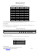
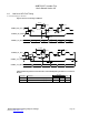
The format for Framed output data is shown in Figure 5-B. Only the bits in the Channel Data Bits are transmitted along with
framing information (data used to locate the start of each frame for proper reconstruction at the decoder) over the channel. The
first 192 bits provide overhead information, which is sometimes useful to the host but is generally not transmitted over the
channel.
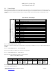
Figure 5-B Basic Framed Output
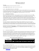
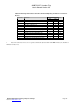
Word # Description
0 Header always set to 0x13ec
1 Power Control ID (8bits) Control Word 1 (8 bits) – see Table 5-J
2 Rate info 0
3 Rate info 1
4 Rate info 2
5 Rate info 3
6 Rate info 4
7 Bit Error Rate
8 Soft Decision Distance
9 Detected Bit Errors in Current Frame
10 DTMF Control – see Table 5-L
(12) 16 bit words of overhead
(192 bits)
11 Control Word 2 – see Table 5-N
12 Channel Data
13 Channel Data
14 Channel Data
15 Channel Data
16 Channel Data
17 Channel Data
18 Channel Data
19 Channel Data
20 Channel Data
21 Channel Data
22 Channel Data
20 ms frame
24 sixteen-bit words = 48 bytes = 384 bits
(12) 16 bit words of data
(192 bits)
23 Channel Data
5.3.1 Framed Output: Word 0 : Header
The header is a 16-bit word that begins each valid frame corresponding to 20 milliseconds of speech. This field will always be
0x13EC.
5.3.2 Framed Output: Word 1 : Power Control ID
The encoder will always use 0x00 in the 8-bit field of an output frame.
5.3.3 Framed Output: Word 1 : Control Word 1
This 8-bit control word indicates the activity of various functions.
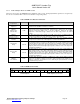
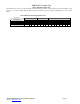
Table 5-J Control Word 1 Format
Control Word 1 – 8-bits (See Table 1-A)
7: MSB 6 5 4 3 2 1 0: LSB
Unused Unused
Decoder
Frame
Repeat
Decoder
Silence
Detect
Unused Unused
Encoder
Silence
Detect
Encoder
DTMF
Detect
Decoder Frame Repeat: When the Decoder Frame Repeat flag is set to 1, the decoder is reporting that the last frame decoded
was a repeat of the previous frame.