
User`s manual

AMBE-2000™ Vocoder Chip
User’s Manual Version 4.9
DVSI Confidential Proprietary, Subject to Change Page 31
Visit us at www.dvsinc.com
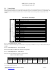
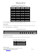
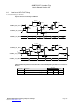
5.2.9 Framed Input: Word 11 : Control Word 2
Table 5-G Control Word 2 Format
Control Word 2 – 16-bits
Bit 15 14 13 12 11 10 9 8 7 6 5 4 3 2 1 0
Decoder Output Volume Control
Unused
0
Unused
0
VAD
Unused
0
SL EC RIS
Decoder output volume control
The default gain value is set to 0x80h
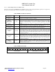
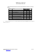
Rate Information Selector (RIS):
Use these 2 bits to select which part(s) of the vocoder will be affected by the rate selection words.
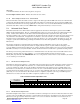
Table 5-H Rate Information Selection Codes
Value Area Controlled
0x0 Encoder and Decoder
0x1 Encoder only
0x2 Decoder only
0x3 Neither Encoder nor Decoder
Echo Canceller (EC):
Set this bit to 1 to enable the echo cancel function on a frame-by-frame basis. This must be set to 1 in every packet sent to
continue use.
Sleep (SL):
Set this bit to 1 to enter Sleep mode on a frame-by-frame basis. Sleep is a low power mode, not to be confused with Power
Down Mode. The sleep function must be enabled in every packet to continue in sleep mode. Set this bit to 0 to exit Sleep
mode.
VAD:
In order to set the Voice Activity Detector on, set the VAD bit to 1. To disable Voice Activity Detection, set the VAD bit to 0.
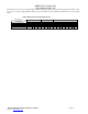
5.2.10 Framed Input: Words 12-23 : Channel Data
This is the field that contains the actual coded bits. Input of the data begins with the MSB of the first word in this field and
continues through with the final bit output being the LSB of the final word. If the data rate selected is less than 9600bps then
the unused bits in each frame are zero and populate the end of the field. As is noted in the Channel Interface definitions, these
unused bits must still be clocked out of the AMBE-2000™. The packet must always consist of 24 words.