
User`s manual

AMBE-2000™ Vocoder Chip
User’s Manual Version 4.9
DVSI Confidential Proprietary, Subject to Change Page 27
Visit us at www.dvsinc.com
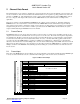
5 Channel Data Format
The channel interface is responsible for outputting the compressed data from the encoder and inputting compressed data to the
decoder. In addition to these most basic functions the channel interface is also capable of reporting certain events, such as the
detection of a DTMF tone. The channel interface can also control certain selectable functions of the AMBE-2000™, such as
the voice coding rate. This chapter will describe how the AMBE-2000™ uses the channel interface to multiplex these
capabilities.
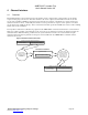
There are two formats to the data, Framed and Unframed, both of which operate in serial mode. Generally speaking the
Unframed mode is used only when the connection between the AMBE-2000™ and the channel under design is relatively
direct, and the designer wants to simplify the extraction of the relevant voice data. In this mode configuration is accomplished
using hardwired pins. In most cases, when a controller is present between the AMBE-2000™ and the channel, the system
designer will find that using the Framed format is more flexible.
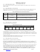
5.1 Framed Format
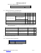
The Framed format is a 24 by sixteen-bit word format for a total of 48 bytes or 384 bits. Every 20 milliseconds the encoder
outputs 24 sixteen-bit words, and likewise the decoder expects to receive 24 words. The format of the input and output frames
are detailed below. The first 12 sixteen bit words are made up of header, ID and status or control information. The remaining
12 sixteen bit words make up the encoded data bit field. These 12 words, or 192 bits, will be fully populated with relevant
voice data only when the AMBE-2000™ is operating in a 9600bps mode (9600 bits/sec ÷ 50 frames/sec = 192 bits/frame).
Otherwise, when the data rate is less than 9600bps, the coded voice bits are filled starting from the MSB of the first word in the
field, leaving any unused bits as zeros. It is important to note here that even when the AMBE-2000™ is operating at less than
9600bps, all 384 bits of the Framed format (including any unused trailing zeros) must be transferred out of the encoder and
into the decoder.
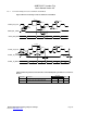
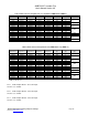
5.2 Framed Input
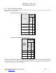
The format of the Framed input is shown in Figure 5-A. Keep in mind that even though the channel data in this Framed input
is closely associated with the decoder, the control information will apply to both encoder and decoder functions.
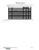
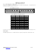
Figure 5-A Basic Framed Input
Word # Description
0 Header always set to 0x13EC
1 Power Control ID (8bits) Control Word 1 (8 bits) – see Table 5-B
2 Rate info 0
3 Rate info 1
4 Rate info 2
5 Rate info 3
6 Rate info 4
See Tables 5-C and 5-D
7 Unused in Input
8 Unused in Input
9 Unused in Input
10 DTMF Control – see Tables 5-E and 5-F
(12) 16 bit words of overhead
(192 bits)
11 Control Word 2 – see Table 5-G
12 Channel Data
13 Channel Data
14 Channel Data
15 Channel Data
16 Channel Data
17 Channel Data
18 Channel Data
19 Channel Data
20 Channel Data
21 Channel Data
22 Channel Data
20 ms frame
24 sixteen-bit words = 48 bytes = 384 bits
(12) 16 bit wor
ds of data
(192 bits)
23 Channel Data