
User`s manual

AMBE-2000™ Vocoder Chip
User’s Manual Version 4.9
DVSI Confidential Proprietary, Subject to Change Page 17
Visit us at www.dvsinc.com
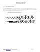
3.4 Associated Chip Delay
The associated delay due to the coding/decoding algorithm is shown below
Encoder Delay
Algorithmic Delay = 32 ms
Encoder Processing Delay = 11.5 ms
Decoder Delay
Algorithmic Delay = 10 ms
Decoder Processing Delay = 7.5 ms
Total Delay
= 32 ms + 11.5 ms + 1 ms* +10 ms +7.5 ms = 62 ms
Frame Processing Delay =
11.5 ms (encoder) + 1 ms* + 7.5 ms = 20 ms
* 1ms of idle time between encode and decode sequence.
3.5 Crystal / Oscillator Usage
The AMBE-2000™ Vocoder Chip has an input clock frequency of 16.384 MHz. Two options are outlined below in providing
this signal. The CLOCK_MODE pin 51 must be set appropriately for the option used.
The following points should be noted when designing any printed circuit board layout:
• Keep the crystal and external capacitors as close to the CLK_I and CLK_I2 pins as
possible to minimize board stray capacitance.
• Keep X2/CLKIN and X1 away from high frequency digital traces (example CLKOUT)
to avoid coupling.
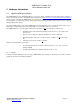
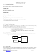
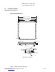
3.5.1 TTL Clock Source
If CLOCK_MODE pin is low then a TTL/CMOS source is used as the clock input. Connect X2/CLKIN and X1 as follows:
Figure 3-C X2/CLKIN and X1 with TTL Clock Source
AMBE-2000
X2/CLKIN (pin 68)
X1 (pin 67)
16.384 MHz
TTL/CMOS Clock
Source
Unconnected
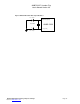
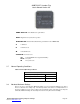
3.5.2 Crystal Oscillator
The Crystal Oscillator option is selected with CLOCK_MODE pin set to a high level. To use the crystal oscillator, connect the
crystal across X2/CLKIN and X1 along with one external capacitor from each of these pins to ground. The recommended
value for C1 and C2 is 10 pF.