
User`s manual

AMBE-2000™ Vocoder Chip
User’s Manual Version 4.9
DVSI Confidential Proprietary, Subject to Change Page 10
Visit us at www.dvsinc.com
+2 dB
0 200 3400 4000
-1 dB
4600
freq (Hz)
-2 dB
3000
-60 dB
-40 dB
-18 dB
8000
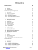
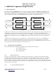
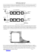
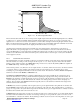
Figure 2 - D. Front End Output Filter Mask
This document assumes that the A-to-D converter produces digital samples where the maximum digital input level (+3 dBm0)
is defined to be +/- 32767, and similarly, that the maximum digital output level of the D-to-A converter occurs at the same
digital level of +/- 32767. If a converter is used which does not meet these assumptions then the digital gain elements shown in
Figure 2 should be adjusted appropriately. Note that these assumptions are automatically satisfied if 16 bit linear A-to-D and
D-to-A converters are used, in which case the digital gain elements should be set to unity gain.
An additional recommendation addresses the maximum noise level measured at the output reference points shown in
Figure 2-B with the corresponding inputs set to zero. DVSI recommends that the noise level for both directions should not
exceed -60 dBm0 with no corresponding input. In addition the isolation from cross talk (or echo) from the output to the input
should exceed 45 dB which can be achieved via either passive (electrical and/or acoustic design) or active (echo cancellation
and/or suppression) means.
2.2.3 Channel Interface Overview
The channel interface is meant to be flexible to allow for easy integration with the system under design. The basic hardware
unit of the interface is a serial port. The serial port can run in passive or active modes. In passive mode, all of the channel
interface control signals are inputs to the AMBE-2000™ chip. In active mode, only the TX_DATA_STRB is an output from
the AMBE-2000™ chip. All other signals are inputs.
Under normal operation, every 20ms, the encoder outputs a frame of coded bits, and the decoder needs to be delivered a frame
of coded bits. There is some formatting of the data for both the encoder and the decoder. The primary purpose of the
formatting is to provide alignment information for the encoded bit stream. The data has two formats, Framed and Unframed.
Serial mode can run in either Framed or Unframed mode.
The Framed and UnFramed Modes are explained in full detail in Section 4, but essentially the two formats are trying to
achieve the same function, to provide positional information regarding the outgoing and incoming coded data streams. In
Framed mode each 20ms of output data from the encoder is preceded by a known structure (each packet corresponds to 20 ms
of speech data input to the encoder). This structure also embeds some status type flags, meant for local control purposes,
within it. The only data from the Framed format that is typically sent across the transmission channel under design are the
actual encoded bits at the desired rate.
In Framed mode, it is the responsibility of the designed system to pass enough information along with the encoded bits such
that the Framed format needed by the decoder can be reconstructed on the other side. This extra information, or overhead, is
going to be very specific to the system under design, but at a minimum needs to pass enough information to reliably reconstruct
the 20msec frame structure at the other end for the decoder.
In Unframed mode the data coming out of the encoder can be thought of as a continuous stream of voice data with the framing
information embedded within the encoded bits. One advantage of this type of set-up is that the system does not have to add
any bandwidth for overhead to the channel. The disadvantage is that the decoder needs 10-12 incoming frames in order to gain