
Product specifications


TeleGroup | www.telegroup-ltd.com |www.telegroup.rs |
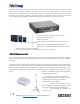
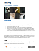
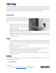
Modular Structure of the FPA‑5000 Modular Fire Panel
Due to its modular structure, the FPA‑5000 Modular Fire Panel provides complete flexibility and thus
customized solutions for any application. Depending on the requirements, the following selection can be
made when planning:
1. Housing type: Frame installation or wall-mount
Selection of a basic housing
Optional Extension Housings
Optional Power Supply Housings
Optional kits for installation in 482.6 mm (19") racks
2. Operating and Display Unit with Panel Controller
Selection from the various language variants
3. Panel Rail
Selection according to housing type and/or number of required functional modules
4. Functional modules
Selection based on planning and country-specific requirements
5. Power supply
Batteries
Additional power supply facilities
Power Supply Brackets are preinstalled ex-works for Frame Installation Housings
For Wall-mount Housings, Power Supply Brackets are selected as needed
6. Additional accessories
Front Doors
Printer with Frame Installation Housing
Cable Sets for special applications
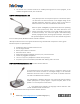
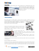
Modules
The functional modules are autonomous, encapsulated units that can be inserted into any control panel
slot using "plug-and-play" technology. Thus, the power supply and the data traffic to the control panel are
indicated automatically without any additional settings. The module is automatically identified by the
control panel and functions in the default operating mode. Wiring to external components is performed
using compact connector/screw terminals. After a replacement, only the connectors need to be
reinserted; extensive rewiring is no longer required.
Networking
Up to 32 Panel Controllers, Remote Keypads and OPC server can be interconnected within a network.
Depending on the application requirements, Panel Controllers and Remote Keypads can be grouped,
defined as network node or local node. Within a group, only panel conditions of the same group can be
displayed. Regardless of the groups, network nodes allow for the display and handling of all panel
conditions. Local nodes display the conditions of the related panel. When networking via CAN and/or
Ethernet interfaces, the following connection topologies are optional:
Redundant loop via CAN1 and CAN2 (max. 32 nodes)
Ethernet loop (max. 32 nodes)
Multiple CAN loops with Ethernet backbone and up to 32 nodes
For networking with optical fibers, you can use various converters.