
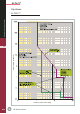
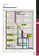
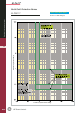
Specifications
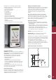
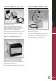
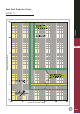

M-PRO17 Microprocessor
Protection Relay
MPRO17 shown with UEF
1.Overload rotary setting switch
2.Short circuit and time delay rotary setting switches
3.Earth fault and time delay rotary setting switches
4.Selectable manual reset button
5.Overload and short circuit protection curve symbol
6.Earth fault protection curve symbol
7.Healthy LED
8.Multi-pin socket for test box and/or portable
power box
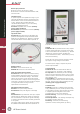
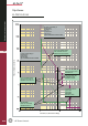
M-PRO20-40 Microprocessor
Protection Relays
1.Overload/short circuit protection curve
incorporating 7 red LEDs; indication of fault type
2.Earth fault protection curve incorporating 2 red
LEDs for fault indication
3.LCD 2-line display for clear indication of menus,
settings, recorded information
4.Warn/Alarm LED
5.Healthy LED
6.Selectable Manual-/Automatic-reset button
7.Four button tactile key pad
8.Multi-pin socket for test box and/or portable
power box
A.12
Technical overview
A
GE Power Controls
3
2
4
8
1
5
6
7
3
4
5
6
8
7
2
1