
Specifications


Single Operator Four Radios (SO4R)
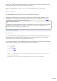
Under TRX1, SO4R check box enables support for Single Operator Four Radios operation.
SO4R has the following (optional) effects:
"Sends" the Transceiver number to the LPT port (parallel band decoder)
OLE, Band decoder, Synchro functions follow the Operating Transceiver (while, if SO4R is
NOT checked, these functions are only activated for the main transceiver).
Support for the launching of registry files at startup (see below)
LPT Port in SO4R Mode
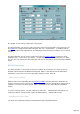
Setting up the parallel port
To use the parallel port in the context of the SO4R mode, you have to set up the band
decoder for a parallel port (the RS232 band decoder is not usable for this application).
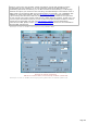
Choosing and setting up the parallel port is made from the BAND DCD tab of the
Parameters/Setup dialog.
Available informations on LPT port
If SO4R is checked, TRX-Manager sends the Operating transceiver 's number as follow:
Pin 14: High = TRX1, Low = TRX2, High = TRX3, Low = TRX4 (CT/WL/TR format).
Pin 2-9, depending on the a b c d flags of the band decoder, the corresponding pins are
activated at a high level as follow: a = TRX1, b = TRX2, c = TRX3, d = TRX4. The purpose
of a b c d flag is to indicate which rig is operating and can be set ON for each band ; of
course only one pin will be activated at the same time: the pin corresponding to the
Operating transceiver abcd means the 4 rigs may be set on. 0bc0 means only rig #2 and
rig#3 may be set ON. etc... If you use rig#1 on all HF bands and rif#2 on VHF bands
(including 6m), you may have a000 from 160m to 10m and 0b00 for 6m to 70cm... If you
use rig #0 or rig #2 on all bands, you will have ab00 on all bands but only one pin will be
activated depending on which rig is Operating.
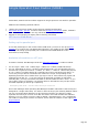
Example by Bob KI2L : A multi-radio LPT Keyer Interface.
One of the challenges when operating TRX-Manager's SO4R in CW mode is that the keyer is
designed for a single radio setup. You have to move the keyer jack manually between radios...
not very convenient. Bob designed a 4 rigs LPT keyer interface: the design is simple,
replicates the LPT keyer once for each data line used in the band decoder that indicates
which trx is in use. These are pins 6,7,8,9 by default, representing trx 1,2,3,4 respectively.
The emitter of each keyer transisor is however, driven from the collector of the original LPT
keyer interface.
Page 154