-
Welcome to TRX-Manager V5 ! Welcome to TRX-Manager, an interactive software for HAM Radio Operators! TRX-manager supports almost all the functions of more than 80 commercial transceivers as well as many accessories (rotators, amplifiers, antennas, keyers, wattmeters...) fully integrated in a comprehensive package for Radio Amateurs.
-
Quick Memories Programmable Band Plan Drag and drop of frequencies between windows OLE Link, compatibility with LOGic, Swisslog High precision S-Meter Macro commands Synchro for SteppIR beam, ACOM2000 amplifiers, third party program and other controllers via RS-232, Linear-Reminder for manual linear amplifier (or antenna tuner) Support for CW Skimmer Support for digital Wattmeter TRX-Pan a Spectrum Analyser for SDR Short wave listening Data base for Short Wave Listening Automa
-
The software runs under any 32 bits or 64 bits version of Windows (Except NT3.51) and supports the following transceivers defined as Main transceiver: YAESU FT-212 FT-412 FT-736 FT-450 FT-747 FT-757GX FT-757GXII FT-767GX FT-817 FT-840 FT-847 FT-857 FT-890 FT-897 FT-900 FT-920 FT-980 FT-990 FT1000MP /MKV FT1000D FT-990 and FT-1000 ROM 1.
-
(F6ELU), RADIO 33 (F5OLS ), ICOM France (F6FOW) John KI4JPL (TenTec) Stan LZ1IU (ACOM) for the technical assistance brought to the implementation of the Yaesu, Kenwood TenTec ICOM ACOM transceivers/amplifiers. Copyright © 1999-2014 Laurent Labourie. All rights reserved. IDDN.FR.001.180003.00.R.P.1999.000.
-
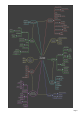
TRX-Manager: features map This diagram shows the various functions grouped by main features.
-
Page 6
-
Getting help TRX-manager features a very comprehensive help system. Most windows have a help button and many controls have touch help. Index is the best approach to search for a specific information using known Keywords. If you don't find you may try the Search function. You may also print any section or all the topic using the Print button.
-
Requirements TRX-Manager requires: Probably a transceiver or a receiver!... A Personal Computer and any 32 bits or 64 bits version of Windows (except NT3.
-
andWiMo (Germany). Other reasonably priced interfaces are available on the market. Cable Generally the cable between the computer and the interface (or the radio) is a straight wired serial data cable (RS232 DB9/DB9). Exceptions are: FT-847 (null modem cable), FT-100 ( Yaesu CT-62 cable) and JRC (special wiring). RS 232/USB converters While a com port on the mother card is always preferable, if your computer does not have a serial RS232 input, you need an RS232/USB converter.
-
The TRX-Manager's band decoder emulates a Yaesu radio on pins 2-5 of a parallel port (other band data formats are possible). Parallel port can also be used for CW keying and is programmable for the control of an external device (such as amplifier...) or for SO4R information. Windows 8/64bits Under recent versions of Windows 64 bits, the LPT driver (third party)may not work. Please note, until now, that no fix is available and that a such fix is unlikely.
-
Installing TRX-Manager TRX-Manager is installed by a program which copies the required files and registers the system resources. Preparing your system for installation Under XP, Vista, W7, W8 You must have administrator rigths to install TRX-Manager. Installing TRX-Manager with restricted rights is not possible. Installing TRX-Manager Licensed version Run your personal file: SETUP_TRX5_DYYYYMMDD_IDXXXX.EXE as downloaded after your payment. Once installed, TRX-Manager must be registered.
-
You may browse AppData\Local\TRX-Manager from the Parameters\Browse submenu. TRX-Tools.exe (distributed with TRX-Manager) lets you browse all the folders that TRX-Manager uses including the Backup folder. Note If you own an older installation (CD prior to 5.0), TRX-Manager switches using the new folder structure.
-
If the folders and registry structure (32/64bits), screen resolution are the SAME on both computers you may use the TRX-Manager.reg file to restore your parameters on a new computer. You may copy all all the AppData\Local\TRX-manager folder to the new computer (using the same location). You still have to register Copying system or executable files For a reinstallation, the installation procedure must be followed completely.
-
Getting started Please run TRX-Manager from the Start menu. Your first session (Setup) For your first session the software prompts you to choose the Language, the IARU Region and pops up the Setup dialog box. TIP For this first session, please KEEP THE DEFAULT settings unless you understand exactly your changes. The only exception is DTR which may be required to power on your RS232/TTL interface (if used).
-
If necessary, you can also access more controls from the Levelswindow ( Transceiver/Levels submenu). Internet TRX-Manager uses Internet Explorer's settings. Please configure you firewall to allow TRX-Manager accessing to the Internet or your personal network. User manual Now, please read some of the help topics... for this purpose, a printable help is available for download from the TRX-Manager's website .
-
Activ ating the Prev ious session option 3) About Time and Date Frequently asked question: When in edit mode (Normal QSO mode) the Log time is 24 hour Zulu format but when switching to List mode the time is displayed in 12 hour am/pm mode? Answer: TRX-Manager follows Windows Regional Settings for Time, date, etc... See also Graphical interface and preferences. Use with old computers TRX-Manager is still compatible with old computers running Windows 95SP1/98 and Pentium II/III 500M/1GHz class processors.
-
Graphical interface and preferences The program allows choosing various preferences from the Preference submenu. Each Tab of the Preferences dialog boxes is related to a particular module. Please click the help button for getting help about the displayed tab. Below, only general settings are described. Interface overview The software uses the Multi Documents Interface system. Each window is displayed inside the same container.
-
Custom buttons It is possible to associate up to five buttons with any program of your choice. Please open the Preference submenu, under software, to associate a button with a program. TRX-Manager extracts the icon so it appears on the tool bar. Please note that the corresponding program opens from its directory. To remove a program, first press the delete button then the button to delete.
-
If the associated icon is not properly extracted (like with MS-DOS programs), please copy the desired icon (16 X 16 pixels) into the TRX-Manager's directory and rename it as PROGi.BMP (i= 0 to 4). Personalized Menus (Office 2000 type) By default, TRX-Manager shows all submenus (menu commands). TRX-Manager'sPersonalized Menus feature enables to focus on just the commands you need and use.
-
You may choose to display the icons related to each tab by checking the Icons check box ( Preferences under Software). Note, on some PC, the size of icons may be too large and cause a wrong display. The Active Resizer check box resizes most windows. It maintains the same proportions and locations of controls relative to one another. This option optimizes the available space but slows down the loading of the program.
-
Setting time and geographical position You have to set up the parameters for Time via the Preferences submenu under Location . By default, TRX-Manager uses the system time; the system time should be equal to the UTC time. If you prefer, or if the displayed UTC time is not correct, you also may use the local time with a convenient offset (PC-UTC).
-
Dates and Times are displayed according to the format defined for Windows : please set these preferences from the Windows's Regional Settings Panel ( Date and Time property pages). Using the period (.) as decimal separator is highly recommended! Please set this parameter from the Numbers property page.
-
Windows layout TRX-manager features various functions relating to the windows. Position and size of the windows All the windows can be laid out on the screen as you wish. Most windows can be minimized as icons in the lower display area but only a limited number of windows can be maximized (i.e. to occupy all of the screen). However, most windows can be resized with the mouse to adjust the size of the characters or the data. Normalizing a window can be done by clicking its title bar.
-
Reorganization of the windows The Windows menu offers the standard Windows's functions: Cascade : positions all the windows in cascading fashion. The windows are resized with their default size. Tile horizontal : lays out the windows - one on top of the other. Vertical mosaic : lays out the windows - one beside the others. Arrange icons : the icons of the minimized windows are re-aligned. Reset : the windows are re-initialized with their size by default without changing their position.
-
Database Grids TRX-Manager uses configurable grids (Infragistics Data Widget 3 library) to display the database ( SW List, LogBook, Prefix...). This section summarizes the common methods for the use and the configuration of these grids. Manipulating and configuring the grids Scrolling the database Scrolling the database is possible using the horizontal and vertical scrollbars.
-
mov ing the splitter Colours Odd lines uses Windows default colours ; colour of even lines may be set from the Preference dialog under Software. Saving a layout Layout changes (position and width of the columns) may be saved by pressing the layout button . The layout is then saved as a .grd file having the same name as the corresponding database; this file will be recalled when opening the database. Example You are working under TRX-Log.mdb.
-
column button Sorting To sort a column, you have to select this column by selecting any record from this column or the header ; an action on and buttons provides sorting by ascending or descending values. Navigation bar The navigation bar provides additional functions : nav igation bar : these buttons jump to the previous/next page/record in the database. (Update) : validates the changes made from the Grid. (Cancel) : Cancels the changes made from the Grid (before validation)..
-
Saving your parameters Saving your parameters The Parameters/Save Parameters subenu saves all your current settings (Setup and Preferences) into a reg file (TRX-Manager.reg). Depending on your system and version, the TRX-Manager.reg file may be located: 1. 2. in the TRX-Manager\Backup folder in the AppData\Local\TRX-Manager\Backup folder (by default since TRX-Manager V5.X) Restoring your parameters To restore your parameters, you have to exit TRX-Manager and double click the TRX-Manager.
-
Saving, restoring your personal files See also : Installation, Reinstallation and the note about the TRX-Manager's folders structure All temporary and utility files are located either in the TRX-manager's main folder or in the ProgramData\TRX-Manager\Misc folder (depending on your CD version and option for Use AppData ). Generally you don't need to save these files... All critical and personal files such as Logbook database (.mdb), SWL (.mdb), MEM (.mem)...
-
Uninstallation Easy and clean uninstallation is provided by using Windows utilities. Automatic uninstallation The software may be fully uninstalled using the standard Windows's utility (configuration panel: Add/Remove applet). During the process, the software may ask you to keep or to remove some of the shared files. You have to select REMOVE ALL for a full uninstallation (including not shared DLL or OCX files).
-
Troubleshooting guide: Installation and use Please read all! This section summarises the most frequent problems (communications excepted) encountered during the installation or the use of TRX-Manager. Please read ALL! How to delete and change parameters without opening TRX-Manager? If you can not open TRX-Manager because of wrong settings and errors at startup, you can delete or change some parameters without running the program. TRX-Manager stores all parameters and settings in the Registry.
-
Some anti-virus using Heuristic analysis are prone to display false positive warnings. If you get a message like "Windows cannot access the specified device, path or file. You may not have the appropriate permissions to access the item", you have to disable your anti-virus during the installation.
-
MSJet35.dll 3.50.3602.4 MSJInt35.dll 3.50.3602.5 MSJtEr35.dll 3.50.3602.0 MSRD2x35.dll 3.50.3602.0 MSRepl35.dll 3.50.3602.0 VB5DB.dll 5.00.3724 VBAJet32.dll 5.0.7122 -2147023067 (80070725) : Automation error This error may occur under Windows 95/98. It is caused by the installation of OLE Automation system files not compatible with your operating system. The following table lists system files required by TRX-Manager under Win XP and Win 9.X : version 2.40 is required under Win9.X while version 3.
-
You may try reinstalling TRX-Manager. Drivers for band decoder not found or not installed (Setup/LPT Tab) Please reinstall the program (or the update); don't forget to reboot your computer to complete the installation. If the problem persists, please ask for a support. Windows 8/64bits Under recent versions of Windows 8/64 bits, the (third party) LPT driver may not work. Please note, until now, that NO FIX is available. Regional settings A common problem may be coming from your Windows settings.
-
This may occur if the little font is selected under Properties for display (Windows) because the program is optimized for the large fonts. It is recommended you set Windows to use the large fonts. truncated labels in little fonts Somes of the windows are truncated or with wrong positions This may happen under XP or Vista if the size (height) of the titlle bar is too large. It is enough to reduce the size of the title bar from the System's graphical preferences.
-
Transceivers: Overview and Settings TRX-Manager can configure up to four transceivers (Setup: TRX1 to TRX4 tabs). Definitions Up to four local transceivers (+ one remote transceiver) can be used at the same time: One Transceiver is called Main and is controlled from the Monitoring window. The Main Transceiver can be selected from the Transceiver menu. The other three Transceivers are called Sub-Transceivers and are controlled from the Sub-Transceivers panels.
-
For a TS-2000/480/590/K2/K3/KX3 (or Remote) transceiver, if you choose the internal CW Interface, check CW Internal (CW via CAT port). For these transceivers any other settings made under the CW tab will be ignored while Internal is checked. PTT options are required in case of you don't use PTT (TX On/Off) via CAT or if your transceiver does not support PTT via computer. TX Interrup settings are rarely used.
-
About com port (main transceiver) The serial port for the main transceiver is opened as soon as the program starts and closes when you exit TRX-Manager; however, it can be temporarily closed using the Transceiver/Com Port. submenu. Whatever its state when you exit TRX-Manager, the com port is always activated at startup. You can check the status of the com port and the transceiver selected from the Parameters/My Configuration sub menu.
-
The Transceiver's preferences are distinct for each Transceiver (Band Plan excepted). Transceiver model and Logging TX Power are also memorized for each Transceiver. Preferences are accessible only during the time the corresponding transceiver is selected as Main Transceiver. If you need a change in the Preferences for a Sub-Transceiver, please define it temporarily as Main from the Transceiver menu.
-
Troubleshooting guide : Serial port The program doesn't communicate with your rig (or your TNC, Rotor...) Of course, anything is possible, but please think first that a programming fault is the less likely. Please read all: almost 99% of the possible situations are covered in this guide and the TRX-Manager's support page! Sometime, the synchronization between the transceiver and the display is lost. It is generally enough to update the synchronization using the Monitoring's Update button.
-
selected (or a generic model is selected), the program may run but with limited functions. Make sure the Com Port OFF function ( Transceiver menu) is not activated. It you find it activated at startup, please exit the program and delete the \Toolbar folder before you restart TRX-Manager. You can check the status of the com port using the Parameters/My Configuration sub menu.
-
this can not solve a communication problem. Moreover, this function is not supported by some comm drivers (like Prolific) and this may lock up the program. Handshaking is only required with Kenwoods, some TenTecs and some serial servers. It is NOT required with other brands and may lock up the program at startup. Should this happen, you have to use the TRX-Tools program (distributed with TRX-Manager) to reset all your configuration to DEMO (TRX1-4= DEMO).
-
required with some serial servers). Step 5 : check your com ports Choosing an USB/RS232 Interface The RS232/USB Converters built with FTDI chips are the more reliable and are strongly recommended! A multi-ports PCI card (internal to the computer) is a very good solution which minimizes RFI and a cheaper alternative to 4 separate USB/Interface Cable. See how to select your converter: http://www.usb-serial-adapter.
-
Test your device (Transceiver, TNC...) with another program. Check the com port has not been disabled by the Bios program (see above). RFI Problems In some cases, especially on 160m, 80m, 40m at high output power, you may have a communication error when transmitting. This is caused by Radio Frequency Interferences ( RFI) between your rig and your PC.
-
ICOM Transceivers This section applies to ICOM radios and TenTec radios using the ICOM protocol (Omni VI and Omni VI). If your transceiver doesn't appear in the SETUP list, please choose the ICOM option which should function with all ICOMs using a generic (but limited) set of commands. Settings Controlling an ICOM via the CI-V protocol requires a CT-17 interface or compatible such as the W1GEE's LCU-3.
-
polls the tansceiver every 500ms since these rigs do not have a Transceive function. Operation The set of commands (from the PC) is variable from one model to the other. Due to the large number of commands available and their diversity, only the most important commands for real-time control are supported by TRX-Manager. These commands are available from the Monitoring and Levels windows. Additional commands can be programmed using macros. Please see your manual for the available commands.
-
Tips by Rich K0FUN When TRX-Manager starts is assumes VFO A is active. If the radio is set to VFO B the program will read this value into VFO A of the program. This can be confusing. The following prevents the problem: 1. With the transceiver on. Start TRX-Manager. 2. Select VFO A from the program (This will insure the Radio is using VFO A) 3. Turn the VFO knob on the radio slightly. This may result in a Dialog Box indicating a Communications Error (Invalid message format).
-
Level, Squelch, APF, NR, PBT , IF Shift, Keyer... Most of these commands are implemented from the Level windows (Transceiver/Levels submenu or Toolbar's button). Controls automatically update at startup; then click ICOM to update the controls. Lev els window (IC-7100) If necessary additional commands may be implemented using the Monitoring's macro buttons or TRX-Command. About the memory channels The number of memory channels (= number of the last channel available) is limited to 99 for all the models.
-
Recent ICOMs (IC-703 IC-746/PRO, IC-R75 and IC-756PRO/PRO2/PRO3 IC-7000 IC-7410 IC-7600 IC-7700 IC-7800 IC-9100) provides editing of the memory labels from the PC (supported). But Destination Call Sign, Access/Area Repeater, Link/Gateway Repeater and Digital Squelch settings are NOT supported. TRX-Manager preserves the contents of the memories on hard disk between the sessions.
-
Yaesu transceivers Related Topics FT-990 ROM1.2, FT-1000 V5, FT-747, FRG-100 FT-1000MP FT-757GX FT-767GX FT-817/857/897 FT-847/736/212/412 FT-980 FRG-9600 FTDX3000 FTDX5000 FTDX9000 FT-2000 FT-950 FT-450 General remarks YAESU transceivers are very different from one model to another. Consequently, many functional differences are possible depending on the transceiver selected.
-
• With FT-890/900 and FT-100 setting the clarifier is not supported. However, the program reads the clarifier and displays the right RX frequency. With FT-840, the clarifier (read/write) is not supported. This could cause the recalled frequency to be wrong. • With FT-920 and FT-1000MP : SWL and BAND SCOPE are running only with VFO A selected, real time scanning functions (up down ) are not supported.
-
Operation with FT-990 ROM 1.2, FT-1000 V5, FT-747 and FRG-100 This section is about the early firmware versions of FT-990 and FT-1000, the FT-747 or the FRG-100. The early firmware versions of FT-990 (ROM 1.2) and FT-1000 (V5), the FT-747 and the FRG-100 do not provide a real time transmission of data such as frequency, mode… You have to select FT-990 ROM 1.2 or FT-1000 V5 in the Setup dialog box to run TRX-Manager (or should this happen FRG-100 FT-747).
-
FT-1000 MP - EDSP and Keyer Controls This section applies to the FT-1000 MP EDSP and Keyer controls. When writing this section of the code with help of Rocco WU2M, we thought it would be possible to control all of the EDSP menu settings via the CAT commands. In fact the problem was more complicated and we have to explain below the logic of the EDSP CAT commands to allow you to understand how to use them from the program.
-
Each time the program sends EDSP CAT commands to the rig, the word EDSP will be prompted in the receive or transmit window. When you close the RX or TX EDSP windows, the program stops controlling the EDSP. The TX-EDSP window also allows you to control the FT-1000MP internal electronic keyer and displays some meter data. For better results We suggest you follow these instructions before starting the CAT EDSP control: 1. 2. 3. 4. 5. 6.
-
Operation with FT-757GX This section applies when using with the FT-757GX Transceiver only (and not the FT-757GXII). The FT-757GX has very few number of CAT control commands. Notably, it is not possible to read the transceiver status (selected frequencies, modes…) and it is not possible to set the mode from the computer! The only CAT commands are : frequency selection, memory operation, toggle from A to B, Band up/down by 500 Khz step.
-
Operation with FT-767GX This section applies for use with the FT-767GX Transceiver. You may run the program as follow: CAT Control Mode To be under CAT control you must press the CAT button (located on the toolbar) or the F9 key. When the transceiver is under CAT Control you will not be able to set things from the transceiver's front panel (as frequencies, mode, functions, etc.) In order to gain manual control, you have to press the CAT button on the toolbar or F9 again to release the CAT control mode.
-
Operation with FT-817 FT-857 FT-897 This section has been written by Rich KOFUN. Due to the available CAT Codes provided by Yaesu there are some limitations in the interface provided by TRX-Manager with the FT-817/857/897. The best way to understand what is possible is to take few minutes and review the available CAT Commands on page 72 (FT-817) 62 (FT-897) 115 (FT-857) of your operating manual. Operational Notes VFO A/B With the CAT Codes it is only possible to switch from one VFO to the other.
-
Narrow CW Filter There is no CAT Command to set Filters on the FT-817/857/897. The Narrow CW Filter Setting in the Parameters - Preferences - FT-817/857/897 - Filters Screen does not any effect. Operating Tips Preferences Use the Parameters - Preferences - FT-817/857/897 Panel to set the following: S-Meter - You may want to calibrate your S-Meter with the S-Meter on TRX Manager. I found mine to be accurate by adjusting the slider three notches to the left of center.
-
Operation with the FT-847 FT-736 FT-212/412 This section applies to the use with the FT-847 FT-736 FT-212/412 transceivers Note that unlike other models the FT-847 requires a null modem serial data cable. Check the menu (#37) on the 847 and adjust the CAT rate at the Setup speed (4800, 9600 or 57600 bauds). The FT-736/212/412 require a standard interface and cable. CAT Control Mode To be under CAT control you must press the CAT button F9 key.
-
It is not possible to retrieve from the FT-736/212/412 current operating conditions. Consequently, you may have a slight difference between transceiver's display and the PC's display, even when controlling the transceiver from the PC, and of course a big difference when controlling the transceiver from its front panel! The FT-212/412 only support setting up of Frequency, CTCSS (Enc, Dec, Tone) and TX/RX switching. All other commands are not supported.
-
Operation with FT-980 This section is only for use with the FT-980 Limitations The FT-980 was one of the early transceivers featured with a CAT Control system.
-
Note the following bug of the FT-980 Yaesu CAT control system : when you run TRX-Manager for the first time after the XCVR was OFF the Width is not updated. HAM and GEN VFO By default TRX-Manager uses: HAM for DX-SPOT frequencies GEN for S.W. frequencies HAM or GEN according to the frequency range for other settings. Please note that the FT-980 CAT sytem doesn't allow you to enter or to change the clarifier frequencies.
-
Operation with FRG-9600 This section applies for use with the FRG-9600 Receiver. The FRG-9600 is poorly equipped in CAT commands. The only available CAT commands are the transfer of a frequency or mode FROM the PC to the FRG-9600. It is thus impossible to read the status of the receiver (frequencies, modes…) or the S-Meter (at least in a digital way). It is also not possible to up/download the memory channels.
-
Operation with FT-450 to FTDX-9000 This section applies for operating TRX-Manager with the FT-450 FT-950 FT-2000 FTDX-3000 FTDX-5000 FTDX-9000 Transceivers. TRX-Manager only supports the latest firmware (PEP) versions; early versions are no more supported. Setting up your transceiver It is recommended to use the maximal available CAT speed (38400 bds). RTS is selectable (recommended if it is correctly supported by your hardware). FTDX9000(PEP): 38400 bds FTDX5000: 38400 bds (menu #32).
-
Possible problems< STRONG> Shift of the frequency when selecting a CW spot: If you notice a shift of the frequency (=Pitch/BFO) when you select a Spot after a band+mode change (i.e CW/40m->USB/20m), please use the CW FREQ DISPLAY transceiver's menu to cancel this shift. Scanning does not stop: During a scanning (SC command), the firmware does not respond.
-
checked). Operation Power On/Off Power On/Off function (CAT button) is supported. Please always power on from the computer if the rig is OFF at startup. However, in some cases, il may be difficult to wake up the transceiver. TRX-Manager features an auto-power on/off function that you can activate from Setup. Dual RX transceivers (FTDX-5000 FT-2000 FTDX-9000) VFO A - VFO B buttons select the VFO and the functions under control (Monitoring and Levels windows).
-
Reading VDD Noise Blanker Levels window: clik the NB (2/1)number to set NB1 or NB2 Contour You can set up CONTOUR (CO) with a PEAK or a NULL using the HIGH/LOW gain switches. Default values may be set using the SET button. CW Keyer Memory (KM1-5) TRX-Manager uses the type 1 mode (Message TEXT). You may set up macros to use the paddle mode.
-
Reverse CW This section applies to FT-990/890/900/840/1000D/767GX/757GXII. These rigs do no feature a CW Reverse function. For these rigs, TRX-Manager makes possible the reception of CW in LSB mode using split mode. Written for fun, you may find it useful ... or not! How to use the CW Reverse function First, it is necessary set up the correct CW Pitch from the Preferences/Transceiver dialog (range: 400 - 700 Hz). Then: 1. 2. 3. 4.
-
Kenwood transceivers This section is mainly related to the older Kenwood transceivers (TS-450, 850...). See also TS-2000 TS-480 TS-590 TS-990 General remarks The Kenwood generic option (Setup) should function with any Kenwood transceiver (eventually not listed) but provides basic functions only and does not allow reading of the data sent by the transceiver. Except for special needs or tests, do not select Kenwood but please select the exact model you are using (i.e TS-XXXX).
-
S-Meter and Band Scope may (sometime) not work properly. Tuning steps TS-450 TS-690 and recent Kenwood provides automatic selection of the tuning step : fill in the Fine Tuning frame under Preferences/Transceivers for Phone and CW/Data. Filters and advanced functions With TS-850 TS-950 and recent Kenwoods, you may couple the filter selection with the variable bandwidth filter (see Modes and filters). Many levels and functions are adjustable from the Transceiver/Levels panel.
-
TS-2000 TS-480 TS-590S/SG Kenwood TS-2000 TS-480 TS-590S/SG are particularly well suited to TRX-Manager. Fully controllable via a computer, they also have a front panel which takes advantage of the TRX-Manager's "computer aided traffic" concept. Consequently, TRX-Manager offers an alternative to the full control via computer.
-
TS-590S/SG/480/2000 share a similar driver and TS-590S or SG are listed in setup. Just for fun, you may select the TS-990 driver by directly typing TS-590 (instead of TS-590S or TS-590SG) in the Transceiver combo box; TRX-Manager will sense your TS-590S or TS-590SG automatically. Layout is different and you may find it more convenient (?), however some features (like Memory channels read/write) are not supported.
-
While the sub receiver has the control, you may use the Edit/VFO window ( F2) or the Up/Down buttons, the keypad and the slider of the Monitoringto set a frequency but the Command Panel is disabled. To toggle from Memory mode to VFO (and vice versa), please use the C button of the Monitoring. The Band Scope has the ability to scan the sub receiver. Generally most of the commands or the modules affect the main receiver only.
-
From the Levels window (Transceiver/Levels submenu), you may set-up the transceiver's parameters or access some menus or functions in an intuitive way. On the left, you will find AF Level, DSP and Squelch controls. The Sub button (TS-2000) gives the control to the sub receiver. This window is updated when opening. Later, the Refresh button polls the transceiver and updates the display. However, if Auto Information is enabled, the levels (on the left) are updated in real-time.
-
internal electronic keyer of your transceiver, A Memory function of the DSP filters is featured, The Pitch=Shift button shifts Pitch and IF-Shift simultaneously Please note that TRX-Manager supports direct CW Keying of the Transceiver via the CAT port. You have to check the Internaloption (Setup/TRX tab) to enable direct CW keying via the CAT port (see also CW Interface). Scan Tab The Scan tab provides settings of the transceiver's scanner.
-
Mode). PCT Mode : the DX Spots are displayed under the DX Cluster tab of the Terminal window. TNC Mode (Terminal) : the button of the Terminal's toolbar switches the TS-2000 into TNC mode. Please note PKT disables the CAT control until you toggle PKT OFF. PKT also disables the Terminal port of TRX-Manager. About PCT Mode While PCT mode is enabled, the commands of the menu (EX...
-
TS-990S The Kenwood TS-990S is particularly well suited to TRX-Manager. Fully controllable via a computer, it also have a rich front panel which takes advantage of the TRX-Manager's " computer aided traffic" concept. Consequently, TRX-Manager offers an alternative to the full control via computer. Setting up your transceiver and TRX-Manager It is recommended to set up the Transceiver for the highest practical speed.
-
The SUB button toggles the active receiver. If the sub-receiver is active, all controls and displays (Levels window included) are related to the sub receiver. The TF-Set function (TFS Button) is supported. In addition, if you give the focus to the TFS button (by pressing it), the keyboard's space-bar toggles the TF-Set function ON/OFF. REV (Reverse) is related to CW/FSK/PSK and SSB Mode (USB/LSB). DAT allows cycling through the three data mode (D1-D3).
-
Like all other transceivers, your TS-990S may be controlled through a LAN or the Internet using the standard remote control mode of TRX-Manager, but with limited functions. However, the TS-990S is well suited for remote control using a serial port server. Limitations TRX-Manager does not work exactly the same as the transceiver with Kenwood's ARCP software. In case of empty memory channels or in memory channel mode, TRX-Manager's behavior may be indeterminate and provide unexpected result.
-
Elecraft K2 K3 KX3 TRX-Manager supports the Elecraft K2 K3 KX3 transceivers. Settings (Setup) It is recommended you set up the Transceiver for the highest practical speed (38400 bds ) ; it is necessary to restart TRX-Manager and the Transceiver after each change of the communication speed. Please check KPA3 or K2/100 is the 100W module is installed (uncheck KPA3 or K2/100 if you use a K3/10 or a K2/10 or a KX3 alone).
-
A combo box provides a direct access to the menu. Notes The AF GAIN and RF GAIN controls cannot be emulated, During edition of a menu or a frequency (direct entry), the TRX-Manager's display is not updated by the transceiver.
-
K3' v irtual front panel (KX3 is different) Colors follow Monitoring's Configuration As the Elecraft K3 KX3 are still in development, some of the functions may be inactive; moreover other functions may be added in the future depending on the firmware development.
-
K3/KX3's menu (8) BAND and MODE switch: Click BAND or MODE to open the Switch. On Switch select TOP to keep it "on top". You may of course use +/- button to scroll through modes and bands... like with a K3/KX3. Band Switch (9) Sliders with double function ; you may also double click the value for a quick and precise change ; press Enter to valid or Escape to cancel.
-
Keyer interface TEXT to Terminal (TT) mode You may use this little terminal for sending text either in CW PSK or FSK! Just type your message and click Enter (or use character/word mode) but please don't forget to turn ON VOX since TRX-manager does not do that for you! Buttons Engages the character mode : the transmission starts immediately after you start typing your message. The Enter key generates the +K string .
-
Since TRX-Manager can not control the CW Pitch of the K3 (until now), it is important you fill in Pitch with the current value under Preferences/Transceiver in order to scale IF Shift range for CW and to center the CW Bandwith. Graphic Equalizer The EQ button (11) opens the Graphic Equalizer from which you can easily display the current settings and set up the 8 bands of the RX/TX Audio Equalization. Equalizer (Bargraph mode) Please press GET to read the current equalization from your K3.
-
output (Audio sound card and KXV3 required). See also Synchronization with PowerSDR-IF or NaP3 using the K3 Synchro mode (alternative to LP-Bridge) K3/KX3 Graphic virtual control screens K3 and KX3 have specific graphic control screens similar to their real front panels. Please use External/Elecraft FP Submenu to display the virtual front panel. Functions are very similar to the K3/KX3's front panel functions however difference may exist generally due to the limitation of the protocol.
-
may also take full control over your transceiver through a network using the real remote control mode : TRX-Manager behaves exactly like if the com port is locally controlled.
-
TenTec Transceivers General information for all models (but Omni VI/VI+) DSP Filtering TRX-Manager implements two virtual filters (Normal and Narrow) for each SSB/CW mode + a Wide filter for AM. Since TRX-Manager uses the DSP, you must check DSP under the Preferences/Transceiver tab and fill in the default values for each filter. If the protocol does not give the ability to set the roll-off value of the DSP, only the total bandwidth is set. See also Modes and filters .
-
OMNI VII TRX-Manager supports Omni VII in radio mode. Please select OMNIVII in the Setup's combo box. DTR and RTS must be checked and communication Speed must be set to 57600 bauds. OmniVII uses hardware handshaking: make sure your cable is wired for RTS Handshaking. It is recommended you set up the Omni VII's Interface menu item to SERIAL IF and not Stepp/IR CT (while TRX-Manager supports both). Almost all main programmable functions including DSP filtering and setting of the levels (AF, RF,Power, ...
-
The roll-off value for DSP is fixed to 200 Hz. BFO (CW) The BFO may be adjusted by using the Pitch function of TRX-Manager (Edit/Pitch) or from the Preferences/Transceiver dialog. The default value is 600 Hz. AF and Line levels These levels are adjustable from the Levels window (Sub receiver level = Line level). AGC AGC is adjustable from the Levels window (1=Slow, 2=Medium, 3=Fast, Off not supported). Argonaut V Please select Argonaut from Setup and check RTS and DTR.
-
Alinco transceivers TRX-manager supports the Alinco DX-77 Transceiver. Setting Please choose generic model Alinco or DX-77 (Setup). Speed is always fixed on 9600 bauds. Limitations It is not possible to upload the memory of the DX-77. The channels are virtual unrelated with the channels of the transceiver.
-
JST Transceivers TRX-manager supports JRC JST transceivers and the NRD-545 receiver with some limitations on program functionality. Settings Choose NRD-535 NRD-545, JST-145 or JST-245 from the Setup dialog box. The JST Protocol is equivalent to the JST-145/245 protocol, however using this setting TRX-manager will not read data from the radio. In this mode, communications speed is fixed at 4800 bps. If necessary, press the CATbutton ( CAT control ) in order to activate remote control.
-
Other brands CODAN NGT Select CODAN in Setup. By convention TRX-Manager adresses the CODAN NGT's Channels by their name (or label) from "01" to "99". Consequently, you have to rename all names by using only 01 02 03... 99. RACAL 6790 Select RACAL in Setup and fill in the Address field. After you restart TRX-Manager, press the CATbutton ( CAT control ) in order to activate remote control.
-
DATA modes. If CW_U gives CW-R on your transceiver, check CW Reverse in the TRX-Manager's Preferences/Transceiver tab. JUMA TRX2 TRX-Manager supports the JUMA TRX2 transceiver loaded with the firmware modified by Adrian 5B4AIY : Version 1.07wb10 or later. You have to configure your Juma with RS232: JUMA TRX2 and (recommended) Baud Rate:115200. TRX-Manager uses the extended auto-information mode of this firmware and simultaneous control of the PA100D is still possible using an Y cable.
-
CAT Programming The CAT Commands window (Tools/CAT Commands submenu) may help you testing and understanding the communication protocol between a PC and a transceiver, its limitations and features. You may send data and read the reply from this window. If necessary, this window may also help you to debug any communication problem by placing a strobe on the serial line to see if the transceiver is communicating. Related Topic Macro commands Old Yaesu transceivers (FT-1000, FT-990...
-
Note A Kenwood (like) protocol has been adopted by Elecraft and Yaesu (from FTDX9000...). However set of commands and parameters may be different from one rig to another and timing (delay between commands) varies from a very fast 20ms (Elecraft), 50ms (Kenwood) to 150-200ms (Yaesu). Anyway, a basic program written for a Kenwood model may function on another Kenwood or Elecraft model and sometime with a Yeasu model; at least if it does not work, it can be easily updated by the developper.
-
Monitoring overview The Monitoring is the main module of TRX-Manager. The monitoring engages a constant communication between the Main Transceiver and the computer and provides real time functions. In practice, the Monitoring window should be always open even if minimized. The Monitoring window looks different according to the transceiver you are using.
-
Frequency resolution: HF 1Hz resolution is not supported by all transceivers (if you note a wrong behavior, please unselect this option). Layout (colors) window Note At startup, TRX-Manager applies Fore/Background colors defined from the Preferences/Software dialog.
-
For each band, the software retains the last visited frequency (+ mode, filter, tuner ) like a band stack register but unrelated with those of your transceiver. The Mhz button displays a numeric keypad from which you can enter a Frequency using the Mouse. QMB Buttons of QMB frame are related to Quick Memories. Clarifier (RIT) If available, Clarifier/RIT shift is displayed (+ R for RX shift and T for TX Shift).
-
very quickly during a session. Interfacing The copy toolbar's button date) into the clipboard. lets you copy the current data's ( callsign frequency mode Update function In some case (after a power on/off or an error), the Update function may be used to resume the communications and synchronize the display with the transceiver. If something wrong appears on the display this function may be used to fix it. The corresponding Update button (if available) is located at the bottom right of the display.
-
Monitoring. The activated controls, the shape and appearance of the window depend on the type of transceiver: Lev els window (FTDX-1200) Lastly if you need some other controls that are not provided by the Levels window, you can use Macro commands either from the Monitoring window itself or using the TRX-Command utility. DX Squelch If AF gain control is supported by your transceiver and according to the status of the Main toolbar's Tools/DX Squelch button , AF is muted after a given period of inactivity.
-
Split operation Various functions make Split operation much easier... Quick Up/Dn function The Monitoring's Quick Up/Dn function allows you switching Split by 1kHz(CW) or 5kHz(SSB) increments very quickly: Quick split by 1kHz or 5kHz increment TXW/XFC/TFS function The XFC (TXW TF-SET) button (Monitoring) makes it possible to quickly set the TX frequency with the tuning dial of the transceiver or the mouse: 1. 2. 3. 4. 5.
-
- This function is only usable if RX=VFOA and TX=VFOB - While TFS/XFC/TXW is activated, the Monitoring loop stops and VFO A can NOT be tuned (improper changes may happen if you try it). - ICOM Transceivers : VFOB tuning is not usable while you hold the ESC key. However, the SUB receiver or the VFOB is selected as soon as you move the mouse over any digit of the SUB/VFO B display and tuning it is possible this way. You have to initialize the VFOB display before using these functions.
-
Undo Redo The Undo and Redo functions (main Toolbars) are running in conjunction with the Monitoring window. They recall the last visited frequencies. When a frequency change is done, the software keeps in memory each frequency visited (up to 10 frequencies): The Undo The Redo button goes back to the last frequency visited, button cancels effect of Undo.
-
S-Meter and Multi-Meter The S-Meter of the Monotoring features two modes of operation/three appearances to be selected from the Transceiver/Layout dialog. All colors of the s-meter are customizable from this dialog. You may also toggle from one type to another by clicking the s-meter. The S-Meter values are not displayed (or irrelevant) during a frequency change.
-
the signal values for the last 30 seconds. Auxiliary Meter (E-Meter) If feedback of meter data is supported by your transceiver, please choose the value to be read (SWR, Po, ALC ...) in the combo box: an additional indicator (analog) or bargraph displays measurement of SWR/COMP/ALC... during transmission.
-
Repeater settings For transceivers which support the corresponding commands by computer, TRX-Manager provides control of various parameters needed for repeater operation. These parameters can be set either from the window.
-
Transverter TRX-Manager provides settings for a Transverter from the Preferences/Band Plan tab. By checking this option in the Transverter frame (Band Plan tab), all frequencies for the specified range will be shifted depending on band switch. I.E You may use a transverter from 28 to 30 MHz for the 144MHz band (with a 116MHz Shift) as follow : To enable the frequency conversion, you must select (using the program) a frequency within the range of the transverter.
-
Frequency editing Direct input The EDIT/VFO menu (F2) opens the VFO window and allows for edition of the current frequency (VFO ). Please note TRX-Manager has been written to reduce typing. To set 14.200, you only need to press the following keys : [F2] [1] [4] [.] [2] [0] [0] [Enter] Setting up current filter, CTCSS Tone, Repeater offset... is also possible from the VFO window. See also : Repeaters settings Mouse input The MHz frame of Monitoring allows a direct input of frequencies using the mouse.
-
Graphic tuning In the lower part of the Monitor Window is an advanced - mouse sensitive (when highlighted) - tuning control. The combo box (on the right) lets you to define the Range (in KHz) of the control (shortcuts PgUp/PgDn). Tuning by moving the cursor The cursor can be grabbed with the mouse ; it is divided into two parts : the lower part tunes over the full range of the tuning control. The upper part fine tunes around the current frequency.
-
corresponding digits. Variable Scanning By holding the left mouse's button and moving the mouse pointer on the right or the left of the cursor you engage a scanning feature for which the speed (or tuning step) is variable and is a function of the distance between the mouse pointer and the cursor. The scanning stops when the mouse button is released.
-
Tuning knob and Scanning Tuning Knob There are two methods to control the VFO button according to the position of the Dial switch. Fast button makes it possible to speed up the QSY. Note that behavior is very different according to the type of transceiver. Tuning knob Dial switch depressed The VFO can be grabbed with the mouse : maintain the left button while making turn the cursor around the VFO knob.
-
By default, the FAST digit tuning option is NOT checked. In that case : - FAST Button NOT checked : a short click allows a precise tuning digit by digit while a long click (>1s) engages a continuous scanning - FAST button IS checked : the short click function is disabled. The continuous tuning is engaged as soon as you click a digit. In the case of the FAST Digit tuning option (Scanning dialog) IS checked, the short click is always disabled.
-
Scanning dialog From the Scanning dialog, you may define: the Lower and Upper scanning limits (MHz) the Center frequency (MHz) and the scanning Range (KHz)...
-
Keyboard tuning The F2 or F3 function keys lets you direct input Frequencies for RX or TX. If Monitoring or DXBar are highlighted, a manual scanning is possible using the numeric keypad (see also keyboard shortcuts ).
-
Joystick Control Frequency tuning and some other functions can be carried out with a PC games joystick or a home made one. Joystick control is supported by the Monitoring module which must be opened. TRX-Manager will use the default joystick configuration on a sound card or USB port. Activation and functions Setting the Joystick is done from the Joystick tab of the Preferences/Transceiver. Once Joystick control has been enabled, each axis of the Joystick must be enabled and calibrated separately.
-
Buttons The buttons have the following functions: button 1 (trigger): this button stops the scanning immediately buttons 2 & 6: centers the action of the joystick without opening the Preferences (both buttons have the same effect : button 6 is preferable since it is located on the base of the Joystick but button 2 may be more easily wired).
-
Wiring a Joystick Note Sound card inputs are rare on recent computers. An USB to game port connectors is a possible and inexpensive solution.
-
Memory channels overview Generally you can toggle the channel memory mode quickly from the Monitoring by selecting a valid channel (using the small arrows) and clicking the [C] button. Depending on the transceiver you are using, selecting an empty channel may load a blank channel or may have no effect (the VFO mode stays selected). The [V/M] stores the current VFO into the selected channel.
-
Please take your time to test it before you purchase the program! Page 120
-
Editing the memory channels Direct editing of memory channels is very easy from the supported parameters may be edited. Edit/Memory Window. Most of You edit the parameters and click Apply to save. You move to another channel by clicking up/down buttons window. or click OK to exit the It is also possible to quickly fill the contents of the memories by drag and drop.
-
Displaying the channels You can view all the content of your memory using the Display/Memory Channels submenu or the following tool bar button . You only need to click a channel number to recall the desired memory channel. The tool bar duplicates main tool bar buttons : creating or saving or scanning the memories ; the Clear All button clears all memory channels in one click (if supported, Kenwood and ICOM only).
-
Skip : Changes the status for scanning Hide : Hides/Unhides the channel (see the manual of the transceiver) Page 123
-
Scanning the channels A scanning “by soft” is possible using the Transceiver/Channels/Scanning submenu. The software provides a signal level floor (S-Units) for busy channels and the scanner pauses and resumes after a preset time delay. With some rigs, you may also use the Squelch to control the scanning: the program resumes the scanning if the carrier drops (only if the Monitoring is running).
-
Creating memory files The program allows you to create memories files on hard disk using the TRX-Manager's file format (.MEM) or the FTBasic's file format (.CSV ). From the main tool bar, click Transceiver\Open to load a file of memories into your transceiver. Click Transceiver\Save to save the content of your transceiver memory on hard disk. MEM files (TRX-Manager) Please read the file section for more information about the *.
-
Files format When you save memories (from the Transceiver menu) the software creates a file with the name of your choice and extension .mem as default. It is a text file. It is compatible with any transceiver supported by TRX-Manager. The content for each line is 13 data's separated by comas (, or ;) in this order : . frequency in MHz (0= > Clear, -1= > Skip . clarifier value in kHz status for tx clar . status for rx clar . status for +RPT . status for -RPT . status for Reverse .
-
INFO.DAT file This file is used to store the current “information” for your memories. It is a text file with: A literal information for each channel (20 characters) 32/90 or 99 lines of text (no blank line) Generally you don't need to edit this file.
-
Band scope overview The band scope function gives a pleasant view of the band activity and provides graphic tuning of your transceiver. TRX-Manager needs to scan the desired band portion to display the spectrum. This scanning may be controlled by the signal strength to pause on busy frequencies. To open the band scope, you need to activate the Tools/Band Scope (Ctrl-B) submenu or the corresponding tools bar button .
-
Red=S9+60dB) ; it is possible to toggle at any time from FS to TFS using the TFS button . Please note that the TFS mode takes a while to draw all the screen. This time depends on the accuracy (1 to 8). Scanning During the scanning, the signal threshold from where the scan pauses is adjustable with the vertical slider. The pause delay (or Scanning delay) is adjustable from the Preferences/Transceiver dialog box. Scanning Step is set automatically in Auto mode or by the user in Manual mode.
-
Band scope parameters Mode (Auto by default) The software scans in CW mode. This is because, in this mode, generally AGC delay is switched to FAST by the rig. You may select manual to scan with the current mode and filter selected but with a loss of precision. Otherwise, the mode determines which mode is selected when the scan pauses: if Auto is selected the program switches to the mode defined by the band plan. Accuracy In Auto mode the accuracy of analysis may be defined from 1 (low) to 8 (high).
-
Sub Transceiver Panel Up to three Sub-Transceivers can be controlled at the same time simultaneously with the Main Transceiver. The Sub-Transceiver control window opens from the Transceiver/Sub...submenu. Only Transceivers supported as Sub-Transceiver are displayed in this menu (see List). Sub-Transceiv er panel It should be also noted that the corresponding serial port only opens when you load the panel and closes as soon as you unload it.
-
Other functions Band selection For each band, the software retains the last visited frequency like a band stack register but unrelated with those of your transceiver. Direct entry of Frequencies Direct entry of frequency is provided from the Band switch (in MHz): A Left click on >RX sets up the receive frequencies while a right click sets up the transmit frequency (TX). Tuning steps (TS+ TS-) Tuning Step is memorized for each Transceiver and each mode.
-
DX Spots From the DXClusteror the WebCluster windows, you may send spots to a Sub-Transceiver without opening the corresponding panel and/or even if it is not the Operating Transceiver.
-
The DX Bar window The DX Bar window (in the Tools/DX Bar submenu) synthesizes the most important information and controls of TRX-Manager for the Operating Transceiver in one easy to operate panel. Unlike other windows, the DX Bar window is displayed outside the main application and remains On Top(according to the position of the On-Top toggle ).
-
Rotator When a spot has been activated, the corresponding azimuth is graphically displayed. The Rotate button controls the rotator and will move it to the corresponding position : DX Spots The DX Spotsreceived from either the Terminalor the Web Cluster are displayed in a simplified format.
-
Note On some systems or computers, opening the DX-Bar window prevents the system menu of the main window from working (especially Maximize, Exit). In that case, you must use the TRX toggle (Maximise) or the Exit button of the DX-Bar window.
-
Quick memories (QMB) The Quick Memories of TRX-Manager are - by definition - simple and quick to use. Using the Quick Memories is recommended in real-time and especially to save DX-Spots. Opening the Quick memory window The Quick Memories window opens from the Display/Quick Memories submenu Ctrl-M). (or Using the QMB Quick memories may be added by Drag and Drop or by using the Paste button. .
-
The context menu (right click) provides various operations with the quick memories and especially direct editing. The Open and Save manages various files of quick memories (.qmb as extension) but please note these binary files are not directly editable. The Erase button erases all the quick memories while the Delete deletes the selected memory. Scanning Scanning the quick memories bank is possible by using the appropriate commands .
-
Page 139
-
Current Spot The Current Spot may be the name of the current channel in use, the SW station being listen to or the last DX-Spotset from a DX-Clusteror a Web-Cluster. This information is bound to the current frequency and will be memorized with the channel, the VFOor the quick memory. It is displayed from the Monitoringor the Sub-Transceiver panels.
-
How to change the modes ? TRX-Manager provides important functions to automate the selection of modes and filters according to your preferences. The Auto-mode function Eventually, you don't need to change the mode: the software does it for you by reading the the Band Plan! By default AUTO-MODE is selected at startup but can be unselected at any time from the AUTO button (Monitoring's or Sub-transceiver's panels). AUTO Mode activated By default, AUTO-MODE is ON at startup.
-
For the Main Transceiver, you may associate a Mode and a Filter by entering your settings from the Preferences dialog under Transceiver. This selection is only valid if the mode is automatically selected by the program (band segment change, DX Spots...). If you change the mode manually (either from the transceiver's front panel or TRX-Manager) the associated filter for that mode is NOT selected.
-
(*) In CW (especially with TS-2000 TS-480 and K3), it is important you introduce the exact value of thePitch (Preferences under Transceiver) in order to set the CW bandwidth correctly.
-
Macro buttons The Monitoring, Sub-Transceiver and Remote windows have configurable Function buttons (or Macro). The Monitoring window supports up to 30 macros. Not all transceivers support macros: generally all Kenwoods and ICOMs, Elecraft and recent Yaesus (FTDX9000 and later) support macro commands. See also TRX-Command (which allows sending powerfull macro commands) via OLE to TRX-Manager.
-
Macro dialog appears after a right click on a macro buttons Selecting a predefined function If you select a function, please make sure the function is available and supported by your transceiver.
-
Multiple commands Multiple commands (in a chain) are possible; the multiple commands are separated by a slash "/" (ICOM, Others) and/or a delimiter ";" (Yaesu/Kenwood/Elecraft). Kenwood/recent Yaesus The command is typed in using the format required by the manual (the last end delimiter “ ;” is NOT required). Embedded commands are supported. i.e Mode USB = MD2 Elecraft See kenwood. I.
-
Audio Gain (Kenwood) Example ICOM : Command for AF gain is 14010000 to 14010255. Syntax = 1401**** (4 digits required) with Min=0 and Max=255 KENWOOD : Command for AF gain is AG0000 to AG0255. Syntax is AG0*** (3 digits required) with Min=0 and Max=255 Sending a command to the Band Decoder Sending a direct command to the band decoder is possible provided: The format of the command is the format defined for the band decoder you are using (Parallel port = 8bits, Com port = ASCII or HEX).
-
Band Plan TRX-Manager implements various functions related to the Band Plan. When you run TRX-Manager for the first time, you are prompted to define your IARU region: Region 1: Africa, Europe, Russia, Middle East (excluding Iran) and Mongolia. Region 2: North and South America including Hawaii, Johnston and Midway Is. Region 3: The rest of Asia and Oceania. You may set Preferences for each band such as Mode and miscellaneous parameters ( Antenna, Rotator, Tuner, Power...
-
Automatic mode switching By checking Auto Mode, automatic mode switching is selected by default at startup. It is always possible to activate/deactivate this function from the Monitoring window (Auto) or a Sub-Transceiver panel for a particular session. The Backlash field (in Hz) prevents from quick and unstable changes of mode near the limits of two segments. Generally 1000Hz is enough. Restoring the default Bandplan If the Auto mode is malfunctioning, your bandplan.csv file may have been altered.
-
Band Decoder TRX-manager can control external accessories (such as automatic selection of antenna, linear amplifier, external controller) by using band data provided on a parallel port or commands sent to an RS232 port. Tip Kenwood does not implement any band data directly on the radio and there is no "Kenwood format". ICOM provides the band data via an analog voltage signal.
-
Select a free COM port and fill in the settings accordingly (do not select Handshaking if your controller does not use it: this may lock up the program). Default command format is ASCII. If you use the Hexadecimal format, check HEX. Band/Segment The Band/Segment option defines the way the band data are defined. If BAND is checked (default), band data are defined for each band (GEN, 160m to 70cm).
-
LPT Band Switch (default = BAND Checked) The length of each string is limited to 8 characters. The band decoder can also be used to send the Transceiver Number to the LPT port (see also SO4R) by configuring the BCD code with with a b c d parameters ; in addition and for compatibility with some applications, TRX-Manager sends Transceiver number (1/3 or 2/4) to Pin 14 .
-
If the commands are documented using ASCII numbers - like chr$(044) - you have to translate ASCII commands into HEXA Decimal: 44 (ascii) = 2C (hexa)... Example: This format must be used with the ProXR Series Relay Controllers, this video by Randy K7AGE Using the band decoder There is only ONE Band decoder ; it is selectable (on/off) for each Transceiver (TRX1-4) from the Rotator/Ant/Misc tab of the Preferences/Transceiver.
-
Single Operator Four Radios (SO4R) Under TRX1, SO4R check box enables support for Single Operator Four Radios operation. SO4R has the following (optional) effects: "Sends" the Transceiver number to the LPT port (parallel band decoder) OLE, Band decoder, Synchro functions follow the Operating Transceiver (while, if SO4R is NOT checked, these functions are only activated for the main transceiver).
-
Multikeyer interface by Bob KI2L Example 2 : Controlling the state of your linear amplifier A specific PIN of the LPT port may be assigned to control the state (Standby/Operate) of your linear amplifier. Of course a very basic interface (transistor, reed relay) has to be built between the remote ports of your transceiver, your linear and the LPT port since TRX-Manager does not control your amplifier directly! The purpose of this sample is to control the state of your amplifier while you are running TRX2.
-
main program folder. If a TRXi.reg file is found the registry keys are set up for the corresponding transceiver (TRX1.REG for TRX1... - TRX4.REG for TRX4). This function makes it possible to switch parameters for an external program, a sound card, etc...WARNING : On VISTA/W7/8 this feature will only work if you run TRX-Manager with Elevated Administrator Rights : "Run as Administrator" checked.
-
Drag and Drop TRX-Manager provides fast transfers of frequencies by using drag and drop. How to ? The drag and drop feature is possible from/between some windows or labels. You only have to hold the left mouse button and to drag the corresponding icon and to drop it into an another label or window.
-
PTT Switching By default, TRX-manager uses a CAT command for RX/TX switching and you don't have to configure PTT switching! However, if this CAT function is not supported (IC-706MKIIG is a typical case), PTT Line switching is possible via the RTS or DTR line of a serial port (CAT or CW Port). In addition TRX-Manager provides a way to read the state of the transceiver's PTT line by using the DSR or CTS line of same serial serial port (TX Interrupt option).
-
interface: in that case, this line (RTS or DTR) can NOT be used for PTT Switching (see the documentation of your interface). (2) If your transceiver requires the RTS/CTS line for Handshaking (Kenwood and TenTec) you can NOT use RTS for PTT Switching (or CW Keying). Whatever the option you choose for PTT switching, the TRX-Manager's CW interface sends a TX/RX signal to its unused line (DTR if you key RTS, RTS if you key DTR...) for compatibilty with Rigblaster or other similar devices.
-
PTT Keying is selected using the CW Port CW Port is COM 13, CW Keying uses DTR PTT Keying is done by RTS on COM13 How to toggle from RX to TX (PTT) Switching PTT ON/OFF is possible from the Monitoring window: Key button or K from the keyboard. Moreover, the CW interface features an Auto TX feature. TX Interrupt (advanced) The TX interrup line allows detection of the RX/TX state via the DSR or CTS line.
-
Synchronization TRX-Manager can synchronize - via an RS232 port - between the transceiver under the control of TRX-Manager and any external device or software which supports Kenwood ICOM K3 protocols: A logging program with CAT Control, PowerSDR-IF (a port mapping software is required or a null modem and two free serial ports) An external device: Tokyo HP, SPE, ICOM PW1 amplifiers, Antenna Tuners...
-
4) By default the Synchronization is only activated for the main transceiver. If SO4R is checked (Setup/TRX1), synchronization is also effective for the sub-transceivers (provided the Synchro mode has been activated for these transceivers). Synchronization starts as soon as you start the program and for the whole session. If the serial port is already in use, an error message is displayed in the status bar.
-
avoids frequent and undesired tuning of the controller near the limits of a segment. Ck Buffer checked is recommended with STPIR. If checked, the program checks for an empty buffer before sending any new command. This reduces the number of collisions but the program may lock up with some comm drivers (like Prolific). The SteppIR window The SteppIR window opens from the Tools/SteppIR submenu and provides various functions and displays. SteppIR Window (DATA-OUT) In some cases of operation (i.e.
-
processor/buffer - THEREFORE - some functions like HOME or CALIBRATE do not always work as expected. PLEASE note the appropriate information in these instructions: If the controller opens Setup while you press Home or Calibrate on screen please switch Power Off/On on controller to resume (a power OFF/ON sequence is always recommended before you start any communication), If Calibrate retracts elements and stops here, press Interface to re-enable the transceiver interface.
-
and COM3 are connected using a null-modem cable. Now TRX-Manager is under the control of your logging program like if it is a Kenwood transceiver... Depending on the program you use (and how it polls TRX-Manager and the flow of data exchanged), connecting two serial ports on the same computer may be critical and can slow down TRX-Manager. Kenwood mode This mode should be always selected to synchronize a logging software.
-
does not poll the transceiver and uses internal data. It is NOT recommended you use this protocol to synchronize a logging software but only to synchronize Power-SDF or NAp3. Indeed some commands sent by a logging sofware which are not supported by TRX-Manager may cause a lockup or a malfunction.
-
NAP3 (Setup-IF panel): Note recommanded Rig timing with TRX-Manager Page 167
-
High Precision S-Meter A high precision S-Meter is installed with TRX-Manager. It is a separate application ( \TRX-Meter\ TRX-Meter.exe) running with TRX-Manager via OLE. Features The TRX-Meter program makes it possible to calibrate a digital S-Meter very precisely; to do so will be require a RF generator. If you don't have a generator, it is still possible to calibrate this S-Meter so that it reproduces the same indications as the transceiver.
-
fixed and not changed. The values read by TRX-Meter are affected by this correction. From TRX-Meter press the CAL. button. Calibration must be done for each S unit (from S1 to S9 and +10 to +60). For each button, set your RF generator according to the corresponding signal strength (value is indicated in µV), then press the button to poll your transceiver; the program is calculating an adjustment factor which will be applied to the read values.
-
This application has been written to the request and with the assistance of Funkamateur Magazine (Werner DL2RD).
-
Linear amplifiers - Overview TRX-Manager makes the use of linear amplifiers easier by providing various functions to automate real-time settings. Related Topics ACOM2000A control (TRX-Acom) Alpha 87A control (TRX-Synchro) Manual amplifiers (Linear-reminder) Synchronization Warning If you encounter RFI (Radio Frequency Interference) on your computer, it can lock up while your transceiver is keying.
-
Page 172
-
Linear-Reminder - Operation Even if you don't own an automatic - CAT controlled - linear amplifier, this little module can be very useful to help you using your manual amplifier (or your manual antenna tuner). The Linear Reminder provides the following functions: Alarm for band changes and cross-mode Display of preset values for Tune Load + 2 user defined fields (USR1 USR2 ) for about 260 segments between 1.
-
Linear-Reminder OPR (Standby/Operate) The Linear Reminder provides a Standby/Operate function (OPR). This function requires a Relay inserted in the PTT line between the transceiver and the linear amplifier (to be controlled itself using the LPT port) or a recent Kenwood transceiver which allows controlling the state of the amplifier relay using a dedicated CAT function.
-
When an alarm happens, please press OK to turn off alarm and re-activate the transmitter or the amplifier. If Auto is NOT activated, only Cross-band conditions will be displayed as an alarm. However, in that case TRX-Manager does not perform any action on the relay or the transmitter. When a Cross-Band alarm prompts, you can turn off Split to turn off the Alarm (or OPR if cross-band is needed). Tune F. and Tune >provides a quick, timed tuning using full or reduced output power (according to your Options).
-
Linear-Reminder - Settings The Linear Reminder module allows numerous settings and configurations. From the Linear Reminder window, click to open the Linear-Reminder's settings dialog. Settings dialog Preset values TUNE, LOAD, USR1, USR2 preset values for each segment: please select a segment by clicking it in the list and edit it by filling in the corresponding text boxes with appropriate values. OPR check box activates (or not) the relay for the selected segment. Press to save the values.
-
Or any preset value of your choice (in W). If the preset value = 0W, the program uses the current power as default. Tune mode This frame defines the way you Tuning Mode (Tuning Mode (FSK is recommended), Temporization for Tune in seconds. OPR/SBY If Control (Control by) is activated, the Linear Reminder provides a Standby/Operate function which may help to prevent from transmitting with the linear on prohibited segments or just after band changes or above a critical drive power.
-
Available options for using a digital wattmeter from the Linear-Reminder module are: Scale of the wattmeter, PTT SWR! Alarm: Keys up the transmitter and/or opens the relay inserted in the PTT line if a high SWR is detected (higher that Alarm Set Point value), Tune Gain: measures the gain of your amplifier. (see Assisted Tune, for Experts). Please let this option NOT checked if you don't use assisted tune.
-
Linear-Reminder - Assisted Tune The Linear-Reminder module measures the Gain of your amplifier and offers a computer assisted tuning method. This last function mimics the alternative tuning method offered by some high-end linear amplifiers generally called Nominal Gain tuning method. It is, however, absolutely necessary to understand the principle before using it safety and with efficiency.
-
Measuring Driv e power Please REPEAT the same operation while using Tune F. (Drive full power WITHOUT amplifier). Then, gradually, as you are Tuning and making gain measurements for the different segments, TRX-Manager will memorize the Drive Power output for each Transceiver (1-4); consequently, it is not necessary to repeat this operation each time you Tune as far as other parameters, for a given segment, remain unchanged (especially antennas and of course Drive power itself see note b).
-
Driv e power v alue lost! Notes (a) If you don't have Relay control by TRX-Manager, please set up your amplifier to Standby/Operate manually and press OPR to indicate TRX-Manager in which configuration you are running your amplifier. (b) If you don't have control of Drive power by TRX-Manager, it is probable you will have to repeat this sequence each time you Tune. In that case, this function is of no great interest...
-
Warning It is important you do not try to maximize Gain which can only result in a signal of poor quality and may damage your amplifier. The objective of this alternative Tune-UP procedure is to reach optimum efficiency while tuning your amplifier for its NOMINAL gain. This ensures transmission of perfect quality.
-
TRX-Acom TRX-Acom software computer controls the ACOM2000A automatic amplifier manufactured by ACOM. TRX-Acom.exe is distributed with TRX-Manager; it may be executed as a stand alone program but installation of TRX-Manager is required. TRX-Acom is usable through the Internet using a serial port server. However, Auto-Tune function may give undesirable behavior if speed of your connection is too low. Also the ON function may be difficult to support.
-
TRX-Acom TOP button keeps TRX-Acom always on top of all other windows. TRACKbutton connects TRX-Manager and TRX-Acom together via OLE. Once TRACK is ON, internal ACOM2000A's frequency counter is overcome, all frequency changes are controlled by TRX-Acom and selected segments are displayed. Note about RCU's PROT Led When an error happens, the amplifiers goes to StandBy. If you press Esc on RCU, error message will be cancelled and RCU's PROT Led will stop flashing.
-
CAT if your transceiver supports setting up RF Power via TRX-Manager, please check POWER VIA CAT and preset required RF Power values in Watts (*) for TUNE and NORMAL: 10-20W of input drive power are recommended by ACOM, select Tuning Mode (FSK is preferable). (*) CAT values in Watts for POWER are indicative values only, not always very accurate (especially with ICOM transceivers) and may require adjustments. You start AUTO-TUNE by pressing START and you follow instructions on screen.
-
Remote control overview TRX-Manager lets you operate any transceiver by remote control through a LAN (through a local area network or the Internet) and even via Packet. TRX-Manager also offers remote operation of rotators and CW keyer.
-
The Transceiver/Remote TRXsub-menu opens the remote control window which allows setting up your network and controlling the remote station (Transceiver, Rotor, CW Keyboard, SteppIR) through a generic interface. Limitations TRX-Manager allows control of virtually all elements of your remote station, economically, without any other equipment than a second networked computer. It's a fun experience and quite effective in DXing.
-
Remote control Settings All settings are defined from the submenu). Remote TRX window (Transceiver/Remote TRX Warning This section describes the specific settings required for remote control. It does not describe how to configure your local (real) station (choices for transceiver, cw interface, rotors...). Please do not attempt configuring TRX-Manager for remote control before your local station (called SERVER) is perfectly operational.
-
UDP: If your computers are connected to the Internet through a Router, you have to configure your Router to route all incoming packets to the corresponding computers on the specified (listening) Port of each computer TCP : Setting up the Router is only required on SERVER. An unique port is used. You SERVER computer is preferably configured with a static IP on your network. This way, your router is configured only once to route all packets to this computer for the listening ports (UDP and TCP).
-
available with a registered version of the program). 1.4) Packet control only Address of the server station : 0 to 9 (the SERVER station must have an address so that several stations can be operated remotely on the same packet frequency) Auto Information : if checked the remote transceiver will notify and confirm to the client station each change of frequency, mode...
-
Typical setup for SERVER and CLIENT using UDP protocol Summary of the main steps 1. 2. 3. 4. 5.
-
small messages to SERVER is possible. However, this capability is essentially written for debugging and should not be used during normal operation. If the auto connect option is checked, the connection is established as soon as you engage the remote control mode from CLIENT (provided the SERVER is running and listening). For more information, please see now Remote control operation. PACKET 1. 2. 3. From the Client's Terminal (TNC tab) you connect the SERVER using your TNC.
-
some specific ports.
-
Remote control operation The Remote interface of the Remote TRX window is simple to use and allows controlling most of the functions of the Remote station. Summary of the main steps 1. 2. 3. 4. 5.
-
Additional macro buttons and sliders are provided to support specific commands for your particular transceiver (see also: Macro buttons). Manual scanning : Each digit of the display is clickable: a left/right click changes frequency (Up/down) by one digit while holding the left/right button scans. gets the current status of the remote transceiver (most important parameters) and updates the display.
-
communication may be a disconcerting factor with a paddle. Paddle EchoBack must be checked (see also Winkey configuration). Note TRX-Manager (CLIENT) does not control your SERVER CW keyer directly ; it communicates with the SERVER instance of TRX-Manager to control your keyer. This why configuring SERVER is important. In addition, there is absolutely no relation between the configuration of SERVER and CLIENT (CW setup are totally different).
-
not supported by the Monitoring window can be used from the IP Control window. The Levels window is not available in this mode (see Real Control mode for using the Levels window). Operating tips The program can check the status of the remote transceiver from time to time using the Update button of the Monitoring. The behavior of TRX-Manager in Remote mode may be different from its behavior with a local transceiver; this mention especially applies to the scanning commands and filters.
-
Page 198
-
Audio transmision TRX-Manager does not support audio transmission many solutions to transfer the audio from SERVER <->CLIENT has been described by users on the TRX-Manager's mailing list. The main possibilities are the followings: Real-time audio link This solution requires a V/UHF link, a phone line or wireless headphones. This solution is probably the best suited for DXing because of the quality of the audio and the lack of delay during the transmission.
-
Remote control Syntax You don't need to learn this syntax; the commands are generated by the program automatically. In case you develop your own interface, the commands available are described below. Sending a remote control command Remote control can be sent : 1. 2. Using the Terminal (IP: Remote TRX, PKT: Terminal ) and the following syntax : TRXi=CMj; i is the address of the remote station (Packet i=0-9, IP i=0).
-
Split : SP 0-1 TRX0=SP1; Sub RX : SU 0-1 TRX0=SU1; TX/RX : TX 0-1 TRX0=TX1; AutoMode : AU0-1 TRX0= VFO : VF 0-2 TRX0=VF0; A= B : AB 0-1 TRX0=AB; Tuner : TU TRX0=TU1; AU0; Tuner start : TT TRX0=TT; Antenna : AN0-1 TRX0=AN0; CAT On/Off : CA 0-1 TRX0=CA; VFO>M : VM TRX0=VM; Status : ? TRX0=?; Rotor : RO Azimuth(3 digits) TRX0=RO030; Rotor Stop : ST TRX0=ST; Rotor Poll : RP0-1-2 RP1; Polling for rotor 1 / 2 (*) TXPower : PW Power (0-100) TRX0=PW30; Page 201
-
AF Volume : AF Volume (0-255) TRX0=AF25; RF Level : RF Level (0-255) TRX0=RF25; VOX : CW : KY string TRX0=KYCQ CQ CQ; VX 0-1 TRX0= VX1; KEYBOARD (*): KB 0-1 TRX0=KB0; CW STOP : KS TRX0=KS; CW SPEED : KW WPM TRX0=KW25; Band Dec.
-
Connect (*) : RC 0-1 (Packet: connection, RC1 enables S1/S2 buttons) TRX0=RC1; IP(disconnects user only) Scanning : SG 0-1 STEPPIR WATCHDOG : SRx (x: H=HOME, I= INTERFACE, S=SET, 0= AUTOOFF, 1=AUTO ON, C= CALIBRATE, N=NORMAL, B=BI-DIR, R= 180°, 3=3/4W, P= POLL) : WD 0000-3600Watch dog delay BAND : BDJ J=Band 0-13 PASSWORD : PAXXXXXXXX; XXXXXXXX= Password (caps ON) UPD LVL (*) : UL (update levels) CAT Cmd : CM (reserved) CAT Status : DT (reserved) Type TRX : TY (reserved) TRX-Command : MA (re
-
OFF : 0 ON : 1 VFO A : 0 VFO B : 1 VFO C : 2 (=CH) LSB : 0 USB : 1 CW : 2 AM : 3 FM : 4 RTTY : 5 PKT : 6 6K : 4 2.4K : 3 2.0K : 2 0.
-
0.
-
Real remote control mode For experts The function described below is only available for the TS-480 TS-590S/SG TS-2000/B2000, Elecraft K2 K3 KX3 and ICOM transceivers. Before reading this section it is recommend you are familiar with the standard remote control interface of TRX-Manager, IP connections and how to configure a network.
-
1. 2. CW Keyer: 2 possibilities REMOTE selected as com port from the Setup/CW Tab (CW Internal, if available is equivalent). You use your keyboard for CW Keying WINKEY is selected and CW Internal is NOT checked: in addition to the keyboard, you can use your paddle connected to the Winkey device for CW Keying 2.1) Remote TRX Same configuration as for the standard control mode using the same protocol as the one set for the SERVER computer (UDP recommended). Operation 1. 2. 3. 4.
-
Alternatives to the remote control function While the TRX-Manager's standard remote control mode (A) is economical, powerful and simple to use, and will work with almost any network connection, there are a couple of alternate methods available which have been used successfully in conjunction with TRX-Manager. Depending on your particular needs, these methods may be attractive to you.
-
The v arious way of remote control using TRX-Manager Page 209
-
Web Server TRX-Manager’s Web Server is a very different and alternative approach to the standard remote control via Packet or IP. Thanks to a Web interface, remote control is possible from any computer regardless of its operating system (Linux, Apple, Android, SmartPhone…) equipped with an audio link via Skype (or other). However, this method of remote control is more limited with less interactivity than standard remote control.
-
Setting up a Linksys Router Note : this setting does not affect Web activities for other computers of the local network since it only affects incoming requests, not outgoing data. It may be necessary to set up your firewall to allow for external requests on the specified port. Setting up the server Port, two cases are possible : 1. 2. Port 80 checked : the port in use is the port 80 (default port for the Web).
-
hides the URL bar on the Safari browser.
-
TRX-Manager from a SmartPhone (Android) Implemented controls are simple and easy to understand. The interface is compact enough to display on small screens. CONTROL (PANEL) opens/closes a frequency/mode... settings entry box. (STATUS) UPDATE is an important button which synchronizes the display of the Web Interface and the real parameters of the station.
-
to activate the Web Server by clicking the OPEN button. If this test is successful, either the addresses are wrong or your router is not properly configured. Please consult the manuals of your devices ; there are 3 main areas to check: 1. the router for correct port forwarding, 2. windows firewall, 3. virus software The Web Interface displays the first time but control is never possible Probably the specified base address is wrong (especially for internet access) or port is wrong.
-
Disabling Dual Control (for experts) TRX-Manager - by default - features a "dual control" of the transceiver: any action on the rig is detected by the program and the new state of the transceiver is displayed by the interface. It uses the full communication protocol and checks that any action from the program has been accepted by the rig before displaying it on the interface.
-
Update button Page 216
-
Sending CW TRX-Manager provides a small terminal (Tools/CW Keyer) for transmission (but not the reception) of Morse code. You may use : The TRX-Manager's CW generator: TRX-Manager keys the RTS or DTR line of a serial port or the Select line of a parallel port. A specific but inexpensive switching interface is required between the com port (or LPT port) and the Key line of your transceiver.
-
Sensitiv e image Mov e the mouse ov er the picture for more information Tips It is suggested that only experienced CW operators use this interface… it is also advised to plug a traditional key in parallel with the PC. You also have to disable the internal electronic keyer of your transceiver. Composing, sending and storing messages Adjust your speed (1 to 50 words minute) as you wish using the slider.
-
The Stop button (CTRL+F12) stops the transmission (sometime with a delay). The detection of a TX interrupt command also stops the transmission immediately. Note If you move the mouse during the transmission, speed will be slowed down or random. Typing your messages Line mode Type your message and press the Enter key: the corresponding line will be transmitted. A buffer allows you to type the next lines without being obliged to wait for the end of the transmission.
-
CW Interface settings This section describes how to configure the TRX-Manager for CW Keying: A : TRX-Manager as CW Generator B : Keying using the internal CAT Keyer of the transceiver C : Keying using Winkey A) TRX-MANAGER AS CW GENERATOR TRX-Manager generates CW and keys the RTS/DTR lines of a serial port or the Select line of a parallel port. You configure the CW keyer from the CW tab of the Parameters/Setup dialog.
-
Serial interface using a reed relay Serial interface using a transistor (positive keying - not isolated) On a DB25 serial port connector, pin 20 is DTR, pin 4 is RTS, and Signal Gnd is pin 7. On a DB9 serial port connector, pin 4 is DTR, pin 7 is RTS, and Signal Gnd is pin 5. A.3) PTT Switching If the CW Port is not the Transceiver Port, TRX-Manager also puts a PTT signal on the unused line of the CW port (not related with PTT switching which is always on TRX port). I.
-
An important parameter is the priority you grant to the CW transmission compared to the other programs. Indeed, Windows is a pre-emptive multitasking system : that means that it shares the CPU time to the various programs to enable them to be carried out simultaneously (at least seemingly). This principle is not very compatible with the generation of CW code! Therefore TRX-Manager sets by default the High priority option which slows down execution of the other programs loaded in memory.
-
Auto TX In CW, automatic switch of the station into TX is done normally by the Break-In or the VOX of the transceiver. In certain cases (use of a linear amplifier or a preamplifier), it can be useful to sequence the switch into TX by first issuing a separate command to close the PTT line before actual transmissions begin. In this case, TRX-manager then operates as follows: 1. 2. 3. 4.
-
2. 3. Switch into TX directly from the transceiver Check that the monitoring indicates TX... in the Status box. If your transceiver does not communicate this data (case of old ICOM transceivers), this function is usable but there is no checking of the state of the transceiver before the sending of CW. Warning In spite of the apparent simplicity of this function, it invokes a complex logic. It is advised to carry out many tests before using it with a preamplifier or a linear amplifier.
-
CW Macros The CW macros are predefined fields made up of the current parameters such as your callsign but also that of the station you're working, his name etc… Extended macros allow you advanced features. Available macros The macros are inserted in the message at the current position of the cursor using the Insert menu.
-
[DATE] [TIME] [STX] : current date - Windows format (Date tab) : current time : serial number (contest) Note Please do not edit the text inserted inside square brackets. This may prevents the program from being able to understand the macros.
-
|: AS _: Space Please see this strange QSO with Gerry VE6LB : @ de µ = tks fer call = ur rst ! ! ! = name * * * = qth % % % = how dr # ? +K Which means : VE6LB DE F6DEX = TKS FER CALL = UR RST 599 599 599 = NAME LAURENT LAURENT LAURENT = QTH LILLE LILLE LILLE = HOW DR GERRY ? +K Extended macros These macros allow you programming of the CW sequencer.
-
Note You must press the CQ Sequencing button and the corresponding message button to engage the loop.
-
CQ Sequencing TRX-manager includes a sophisticated CQ sequencer. Principle The cycle button makes it possible to launch a loop of CQ calls (or any other message). The delay between calls (CQ Delay) is specified from the Setup under CW (Pause mode is the default). This is the delay between the beginning of the first CQ and the begenning of the second CQ (this delay includes the duration of the CQ call).
-
CW Characters set TRX-Manager provides support for most of the Morse characters. However some characters are not used very often and thus ignored by most HAM operators. The Special characters option (Setup ) allows you to disable these characters. Not supported by Winkey or a Kenwood CAT interface. Standards characters alphabet A-Z number 0-9 standard punctuation = / + ? Special characters ÉÈÇÄÀÖÑÜÅ punctuation - ( ) .
-
Winkey Interface TRX-Manager provides extensive (local) support for the K1EL's Winkey & Winkey2 interface. Winkey2, WKUSB TRX-Manager automatically detects Winkey2. Configuration panel slightly differs taking advantage of specific Winkey2's functions. In addition, if you use WKUSB you may assign each Winkey's PushButton either to a message (macro undchecked) or a macro-command (macro checked) to be sent to your transceiver.
-
Winkey configuration dialog ENLARGE the window if this icon does not appear Please see Winkey's user manual for more information about the parameters. Some of these parameters (Weighting, Dit/Dah ratio, Key comp, Port) are saved BY Transceiver (TRX1...4). Prosigns TRX-Manager's prosigns (see Macro) have the priority over Winkey's prosigns and can not be (re)defined. TRX-Manager's CW special characters set is not supported by Winkey.
-
Change Speed Buffered and Cancel Buffered Speed Change functions are supported by inserting macros into your messages : [S:wpm] : to change Speed and [B:] : to cancel Speed change with wpm is the desired speed in Word per Minute, HSCW Speed change is supported by inserting macros into your message [H:lpm] where lpm is the desired speed. Use [B:] to cancel HSCW Speed change.
-
CW Skimmer Interface CW Skimmer by Alex VE3NEA is a panoramic, multi-channel CW decoder and analyzer. How to synchronize with CWSkimmer TRX-Manager provides different ways to synchronize with CW Skimmer. Telnet Link CW Skimmer has a built-in "read-only" Telnet cluster server. The clients can connect to this server and receive DX spots.
-
2. frequency (LO Frequency) and the Pitch . Some adjustements of LO frequency may be required to synchronize the programs. You use a panoramic adapter centered on the transceiver's local IF Frequency (typical setup for a K3 + LP-Pan): under the Radio tab, please choose SOFTROCK-IF option and fill in Pitch and Offset with the correct values.
-
Using TRX-Manager and CW Skimmer together (Telnet Link) Note Please launch TRX-Manager BEFORE CW Skimmer (to prevent CW Skimmer from opening the serial port). Please open the TRX-Manager's Terminal and under Telnet 1 or Telnet 2, connect CW Skimmer.
-
DXCC Window TRX-Manager searches for geographical information from the prefix of a station. This feature is activated from the Display/DXCC info… (F7)sub menu or the button of the main toolbar.
-
TRX-Manager determines the country starting from the left character : it may be necessary to force a country by adding the corresponding identifier or to force the DXCC Code from the Logbook (see Updating DXCC codes). Edition of the prefixes DXCC Information is located in the PREFIX.MDB database. This database may be edited under MS Access 7 or from the integrated editor.
-
DXCC Award status TheARRL DX Century Club awardstatus for a given country may be displayed from the DXCC Window. This ability is only provided for QSOs with a valid DXCC country code (see updating the DXCC codes). P=Phone C=CW D=Data G= Status for GridSquare The program displays the DXCC for the selected country in the form of squares color. The square corresponding to the current mode and bands is in evidence. In addition, the G row indicates if the 4 digits GridSquare has been worked/confirmed before.
-
Please see how to update the DXCC codes to understand the program's limitations. More reports This DXCC information has been conceived as a real-time help to DXing and not as a comprehensive DXCC report. A summary is provided, however for getting most comprehensive reports, you need to export your new QSOs to your main logbook program from time to time or to use the Logbook's Explorer.
-
Updating the DXCC codes To calculate the DXCC status, TRX-Manager uses the DXCC field and not the country or the callsign fields. That means this function is only working if your QSOs have been logged from TRX-Manager or imported from a log program (using the ADIF format) which fully support the DXCC country code (such as LOGic). Note DXCC codes lower than 0 are provisional (until the release of the official ARRL DXCC code) and are not exported.
-
Deleted countries TRX-Manager is not able to distinguish QSOs worked with deleted countries from those worked with active countries. All QSOs will be associated with an active country. However, you may fix that limitation by manually forcing the DXCC codes (or ADIF codes). See below ADIF codes for the deleted countries : Code/Deleted countries 2 ABU AIL IS 8 ALDABRA 19 BAJO NUEVO 23 BLENHEIM REEF 25 BRITISH N.
-
164 MANCHURIA 178 MINERVA REEF 183 DUTCH BORNEO 184 NETHER N. GUNIEA 186 NEWFOUNDLAND/LAB 193 OKINAWA 194 OKINO TORI-SHIMA 196 PALESTINE 198 PAPUA TERR 200 PORTUGUESE TIMOR 208 RUANDA-URUNDI 210 SAAR 218 CZECHOSLOVAKIA 220 SARAWAK 226 SAUDI/IRAQ N.Z. 228 SERRANA BANK 229 GERMAN DEM. REP.
-
VUCC Award TRX-Manager provides various function to track the progression of your VUCC (VHF/UHF Century Club Award ). From the DXCC Window TRX-Manager displays the status of the VUCC Award for a given gridsquare from the DXCC window as well as the corresponding QSOs for this gridsquare by clicking a colored square. The VUCC Summary A summary of this award is available for the 6m, 2m, 70cm and SAT bands (HF bands excluded) from the Display/Awards Summary/VUCCsubmenu . If DXAtlas (V2.
-
IOTA Award TRX-Manager support IOTA Award tracking (Island on the Air, RSGB) . IOTA Information The IOTA Icon opens the IOTA information window.
-
Selection by Continent or Region is possible (WI=West Indies, BI=British islands, AI=Antartic Islands).
-
WAZ, WAS Summary The Display/Awards WAZ WAS submenus open the summary for WAZ (Worked All Zones) or WAS (Worked All States). WAZ and WAS have a very similar appearance. All combinations of modes and bands may be displayed. Initially, the combinations are displayed for all modes (mixed). You select the mode from the Mode combo box and the valid combinations for the corresponding specialty awards are displayed in color. The total of QSOs is displayed in the first row.
-
DDFM and DPF awards TRX-Manager can calculate the progression towards the DDFM award (award of the departments of the Metropolitan France) and the DPF award (award of the French provinces) in their various combinations. Precondition As a preliminary, it is necessary to update the DXCC codes so that the French stations are recognized. Progression The progression towards the awards is obtained by the Display/Awards Summary/DDFM/DPF submenu.
-
Other Awards Other awards or reports can be computed, displayed and saved from the Logbook's Explorer. The first action is to select the valid QSOs by using the search functionor a SQL query (some queries are preprogrammed for the most current awards). Then, the Explorer tab of the Logbook makes it possible to set the fields to sort and to display the database with a hierarchical structure.
-
Prefix and Special Callsigns data base editing Any modification of the Prefix database or of the Special Callsigns database may be performed by opening the Prefix database editor (Edit/Prefix base submenu ... ). Note Please close the SWL and Logbook windows before opening the prefix database from TRX-Manager.
-
Editing the Special CallSigns database Editing the Prefix database Warnings The format of the Prefix and DXCC table must strictly match the format required by TRX-Manager. A wrong format can cause malfunction and erratic behavior of TRX-Manager. As a precaution you shouldbackup the original prefix.mdb database before doing any change. At any moment, you may cancel your changes by using the Cancel button. Please note the Prefix database (Prefix.
-
The Prefix table This table keeps all prefix combinations and associations (2800 entries)... The Prefix table includes the following fields Prefix - DXCC - Longitude - Latitude - Continent - CQ Zone - ITU Zone - Territory . This table allows you to associate a given prefix with a DXCC country and any of these geographical data. Notes Warning: you must use a reference to an existing DXCC prefix of the DXCC table.
-
Azimuth information Each time you type a new callsign in the DXCC window, TRX-Manager shows the corresponding azimuthand DXCC award information and reports the corresponding information into the DX Map. HF Propagation predictions may be displayed. TRX-Manager also calculates distances and directions based on grid squares(at least 4 digits) and provides an interface with DX Atlas and Google Earth .
-
Rotator control TRX-Manager can control a rotator via a com port or a DDE interface. Settings It is possible to define up to two rotators from the Setup dialog box under Rotator (but only ONE via DDE is supported). The program is compatible with: The SARtek-1 universal rotator interface (Azimuth) Yaesu/Kenpro rotators (Azimuth and Elevation) Orion PA PX and PX V2.
-
You must indicate the path of the EXE file (interface) in the Setup's panel. If the interface doesn't work properly, please exit the interface and let TRX-Manager automatically launching it at startup. Please note TRX-Manager supports only ONE DDE Rotor Interface at the same time. Under Vista W7, running TRX-Manager with administrator privileges (or with UAC = OFF) is mandatory to establish the DDE link. ALFASpid Rotators The AlfaSPID rotators may be controlled via two ways : 1. 2.
-
Because of the ease of remote controlling, you may forget the mechanical limitations of your rotator: please make sure that you read and respect the factory limitations. Satellite interface The Satellite Interface supports a direct control of the rotator in Azimuth (and Elevation with some rotators : see above). If you wish your rotator being controlled in Elevation, please check the Setup's Elevation option and indicate the maximum elevation (90 ° by default).
-
DX map TRX-Manager provides an azimuthal projection of the 25 last DX-Spots or the NCDXF's HF Beacons. This feature may be activated from the Web Cluster'sor the DX Clustertools bar The same window shows location for any spot you are listening and controls the rotator. . MAP centered on France - Bitmap generated by LOGic Refreshing the map The Map may be manually or automatically refreshed after each download from the Web Cluster if the corresponding option is checked (Preference submenu).
-
Any left click on map draws a vector to aim the direction. You only have to press the rotator button to rotate the antenna. Loading a map This projection will show up on any background of your choice. Of course it would be interesting to choose an azimuthal map as a background but TRX-Manager is not able to create the map . You must use a separate program to create a map and you need to save the corresponding image as a BMP or JPG file ; then you load the map into the window using the open filebutton .
-
HF Propagation Predictions TRX-Manager includes HF Propagation predictions via the F2 Layer from the DXCC window. Displaying the predictions Once DXCC Info window is open, you only need to click the main azimuth indicator in order to toggle to the HF Propagation prediction mode. Predictions are then displayed for the current country according to a diagram with indication of maximum and lower usable frequencies ( MUF/LUF) for each hour of the day.
-
Short/Long (Path) buttons are activated, by clicking the DX Map you may obtain prediction for the corresponding zone, predictions are calculated for the current day of the current month. Principle TRX-Manager is inspired from R. Fricker's algorithm written in 1985. The program cuts the path into Hops of about 4000 Km. For each control point, the program calculates the maximum usable frequency (MUF) for a reflection through F2 Layer.
-
Interface with DX Atlas TRX-Manager provides an interface with DX Atlas written by Alex VE3NEA. DX Atlas Download Afreet Software, Inc.www.dxatlas.com Installing DX Atlas DX Atlas must be properly installed ; in that case TRX-Manager automatically detects its installation and there is no special settings to do : the DX Atlas's icon appears in the External menu and in the External tool bar. If this icon does not appear, please reinstall DX Atlas.
-
Path from your station to the DX From the DXMap, you can click on the DXAtlas button on its toolbar, which then shows the path between the spotters and the DX spots. This can then be used to show the propagation between your QTH and the DX. You can also right click'on a DX spot and chose DXAtlas to show the propagation between your QTH and the DX. paths between the spotters and the dxspots From the VUCC Award summary window, the DXAtlas button creates the necessary files (trx-manager.cfm & trx-manager.
-
VUCC progression displayed by DXAtlas • Possible problems If you launch DX Atlas from TRX-Manager, you will have the preferences for DX Atlas defined by TRX-Manager (recommended). It you prefer your own preferences for DX Atlas you must launch DX Atlas before you start TRX-Manager. Sometime the computer crashes while launching DXAtlas from TRX-Manager. This problem is probably related to the video-driver but remains unresolved.
-
Interface with Google Earth TRX-Manager provides an interface with Google Earth. The Google Earth application (V5 or later) must be installed on your computer. A google Earth icon appears in various modules : Logbook, CD-Rom (RAC, Buckmaster, QRZ.COM), DX Cluster, Web Cluster, Quick Memories, SWL Database... Each time you press a Google Earth icon, TRX-Manager creates a TRX.KML file and opens Google Earth. The display depends on the context and may include a single station or paths to different stations.
-
Logbook: Selection of QSOs From The DX Cluster, Web Cluster... the context menu allows you to display the position of the selected station while from the toolbars you can display all spots (posted within the last hour) with paths either from your station or paths from spotters to DX Spots. Pin's color follows the DX/Web Cluster convention (red: new one, green:needed, yellow:optional).
-
Context menu : location of the selected station Paths from Spotters to DX Spots Page 266
-
Page 267
-
Log book overview TRX-Manager is not a conventional logging program but provides a very intuitive real-time logging... TRX-Manager uses the very reliable Microsoft Jet 3 data base engine (Access 97 base format).
-
An editing tab to input a new QSOor edit an existing QSO, A listing tab using a configurable grid for a general view of the data base, QSO selection or sorting by any field, An Explorer tab which displays a Hierarchical view of the database, A data control(navigation bar) to navigate inside the data base. Setting up your Preferences Before you use the Logbook, it is recommended you set up some Parameters under Preferences/Software dialog (Logbook tab).
-
Ultra Fast Logging: If checked, pressing F12 or Enter (depending on your choice) populates the fields and saves the QSO in one click (however, only if the if the cursor is in the CALL field. F12 is recommended in most case and Enter only for small keyboards and should be used for Contestonly. See also Logging a new QSO. Expert mode: the Expert option removes real-time message boxes (confirmation for Save, Clear...); in addition Frequency and Mode fields are continously updated.
-
Logging a new QSO Press the new QSO button (or Ctrl-N) to create a new QSO. The button looks as if depressed and the title bar shows : New QSO. Please introduce the callsign and press the TAB button. Use the TAB key to move from one field to another in the log panel. Use the more button to access more fields. The clearbutton ( Ctrl-D) may be used to clear all the fields and to start logging again. Use Ctrl-C to give CALL field focus. The Log button (or CTRL-S or F12 ) saves the QSO in the database.
-
Different buttons have an automatic recall function for some of the current data such as DX-Spot,DXCC country - continent - date - hour - frequency - RST - comment - QSL manager. A one key recall is provided by using the Spot button : Press the Spot button at the beginning of the QSO with a DX (Spot) and press the Log button at the end.
-
while QSL_VIA is for the QSL Manager (if required), the QSL_SENT_VIA field is related to the way you send the QSL : B=Bureau D=Direct E=Electronic Saving the QSO When all the desired fields are filled in (at least Callsign and Date ON), the contact may be added into the data base by pressing the Logbutton or Ctrl-S or F12 ; please note the Date_OFF is automatically updated. The log book is now ready for logging a new QSO and, eventually, may be minimized (*).
-
Editing a QSO To select a QSO for edition, you click the corresponding row of the Listing to make that QSO current. Then select Edit tab and the log book toggles to the edit mode: The new QSO button looks as unpressed, the title bar shows Edit Mode and the fields take the colors of the grid (this last functionality can be disabled by unchecking the Edit Color check box under Preferences/LogBook).
-
The QuickLog window (Duplicate context submenu) A multiple selection function is provided for deleting, logging OFF, QSL=Y and exporting status by selecting one or more QSO using CTRL + [Click] Press ctrl+click to select more than one QSO Quick Edit from the QSO Before window The QSO Before window may prompt to show your previous QSOs with a given Callsign (from the DX Cluster, DXCC Window...). By just clicking a row, the corresponding QSO becomes the QSO current in the Logbook and is ready for editing.
-
QSO Search, Sorting Various searches or selections of QSOs can be performed using the Select function/menu of the Logbook: Quick search for the current callsign Access to the Search window Selection of valid QSOs for some pre-programmed Awards (see also Explorer). The Select button is toggle: click it for a search and click it again to cancel the the search criteria. The number of selected records is displayed on the tool bar .
-
Searching by call sign You only have to type the desired callsign (or a part of a callsign) to search and press OK : the only matching QSO's will be displayed. Searching by date or QSL You have to check the corresponding check-boxes and to fill in the field criteria in order to search. You may also combine date with QSL or call sign by checking or unchecking appropriate check-boxes. Search by location Search can be performed by DXCC country or by State (= French Department for example).
-
Logbook's Explorer The Explorer tab of the Logbook displays a hierarchical view of the database. This very powerful and easy to use function (coupled with the search function), makes it possible to display and to save various reports for almost any award or to seek the database for specific records.
-
When you click a QSO ( may modify its content. Worked, Confirmed) it is displayed under the Edit tab and you The Contest and Dupes options allow displaying the QSOs of the current Contest and/or the duplicate QSOs (or Dupes : same Call, Band, Mode). When Dupe is checked, clicking a QSO from the Explorer selects the duplicate QSOs from the database (in Select mode) and they are displayed in the Listing tab for editing.
-
Tips When you work with the Logbook's Explorer, it is advised to close the Monitoring and windows in order to improve the speed of the program, Sorting by Award takes less time, Sorting is processed by alphanumeric order which is not convenient for some numeric fields such as CQ or ITUzones. It is recommended to fill in these fields with two digits (i.e. Zone 01 and NOT Zone 1). Note that DXCC Update is reformatting ITUZ and CQZ fields with two digits.
-
Advanced searches and reports The Advanced tab of the Log book's Searchdialog box allows you to select records using SQL queries. Some SQL queries are preprogrammed for the most current awards. Below are also some useful examples of SQL queries which can be copied and pasted into the SQL editor. Easy way to search Clicking the Select SQL Adavanced tab. button of the Logbook's opens the Search dialog box.
-
Enumerating SELECT DISTINCT STATE FROM LOGBOOK WHERE QSL_RCVD='Y' AND (DXCC = 291 OR DXCC = 110 OR DXCC = 6) AND STATE <> ' ' ORDER BY STATE Valid QSOs for the WAS SELECT * FROM LOGBOOK WHERE QSL_RCVD='Y' AND (DXCC = 291 OR DXCC = 110 OR DXCC = 6) AND STATE <> ' ' ORDER BY STATE< /FONT> Enumerating a DXCC with QRP condition (10 w) SELECT DISTINCT DXCC FROM LOGBOOK WHERE QSL_RCVD = 'Y' AND TX_PWR < '10' Enumerating the DXCC Millennium award The DXCC 2000 Millennium Award rewards QSOs made with more than e
-
Printing the Log book Printing of the essential data is provided via the corresponding tool bar button . If a search is in progress (Select button pressed) the corresponding selection will be printed ; if there is no search in progress, a dialog box prompts for the selection of QSO to print (by date and/or by export field). The printed log book is sorted by Date ON.
-
QSL Labels printing Printing QSL labels is possible from the Logbookby pressing the button of the toolbar. Selecting the QSOs The program prints the labels of all the QSOs of the current selection whose QSLS field is R or Blank and QSL_Print field is not N. You can modify the current selection by using the Select button (in that case, please avoid to select by QSLS) : i.e, you may select specific QSOs using the QSL_Print field (QSL_Print=L).
-
The message (to be defined from the Preferences or the Log Book) may include the following joker * which will be replaced by the Name. Example: Laurent F6DEX has made a QSO with Pierre F6HAC. The message is defined as : '73 Dear * de Laurent F6DEX' The printed message will be : '73 Dear Pierre de Laurent F6DEX' Printing - updating the Logbook The Page by Page check box prints one page by one page. Printing is launched by the Print button. Labels are sorted by Callsign.
-
Opening and creating a new Log book Creating a new Log book is easy by using the Openbutton . You have to choose the MDB extension and to type -if necessary- the name of the new data base. If this data base doesn't exist TRX-Manager will create a new one; the new data base becomes the current data base. It is also possible to declare the name of the (new) data base via the preferences dialog box logbook tab.
-
Contest Mode The TRX-Manager’s Contest mode allows contesting without necessarily using specialized software. In Contest mode, the Logbook is configured in a very convenient way and some actions like sending CW messages, serial number are automated directly from the Logbook. Export using the Cabrillo format is supported. Setting up TRX-Manager for a contest Contest set up is done from the Parameters/Contest dialog. You enable/disable the Contest mode by checking/unchecking the CONTEST MODE option.
-
ccccccccccccc.rrr.iiiiiiii Each character represents a field and the number of characters = the length of the field, as follow: Once these data are completed, you still have to define, if applicable: RX Optionnal : field of the database to be automatically populated from the SRX_STRING (INFOR = Info received) field. I.E you may decide to transfer the content of the INFOR to one of the standard field of the database like CQZ, ITUZ...
-
Info rcvd (RX) cccccccccc.nnnn.p.tt.iii Info sent (TX) cccccccccc.nnnn.iiiiiiii In that case, data sent (p ck sec) are concatenated in the STX_STRING field of the database: iiiiiiii Data received ck is stored in the Track field (tt) of the database. Logging during a contest Once the Contest mode is configured, you may enable/disable the Contest mode using the Logbook's Contest toggle . Appearance and behavior of the Logbook are slightly different than from the standard mode.
-
Logbook in Contest mode CW Toolbars activ ated Dupes are indicated by a red square Some useful shortcuts (*): Click « Enter » while the cursor is in the CALL field to populate other fields.
-
- Press F1 for a new call... Statistics In this current version of TRX-Manager, no detailed statistics are provided.
-
Importing and exporting the Log book - overview TRX-Manager is able to export data using ADIF (Amateur Data Interchange Format), LOG-EQF (V8 & V9) and CSV formats (Excel). ADIF can be used to exchange with most other programs while CSV (Excel delimited text format) allows you to create various reports. CABRILLOis required to submit your contest log to the Sponsor. Note Importing data usingADIF, LogWindows and TRLog is supported (ASCII formats).
-
Importing is done by pressing the Open button of the Logbook ; the choice of the format is made through the Windows common dialog box (Open… ) : During import, the program may report errors(incorrect or empty fields) ; these errors are frequent but often without consequence. After the file has been imported, you have to perform a DXCC Update from the Tools menu in order to update the DXCC codes as well as CQ and ITU zones.
-
Page 294
-
Logbook Of The World TRX-Manager can create files for submission of your logbook to the ARRL's Logbook of the world (LOTW) as well as update your database from an LOTW's ADIF Status report.See also : Logbook Of The World (ARRL) Creating a file for submission The TQSL program (V 1.13 or later) provided by ARRL must be installed and running on your computer. You must have access to the LOTW website and a valid certificate. No support can be provided for the use or configuration of the LOTW nor TQSL.
-
Exports only QSOs with Export field checked QSO are unchecked after you click SIGNS(TQSL) The LOTW button opens the LOTW WebSite using your login and password.
-
QSL_RCVD is updated to D for all v alues of QSL_RCVD (Y excepted) If the new digitally confirmed QSO has valid fields for CQ Zone , ITU Zone, State, GridSquare, Continent or IOTA, your database will be automatically updated with these v alues. (*) If you open a report with .adi as extension, please make sure TRX-Manager recognizes it as a LOTW report and displays: LOTW Report found... (and NOT “This action will add.” .. which may add the qso to the database!).
-
From the LoTW dialog ( Logbook), click LIST and select the list using the text format (.txt). TRX-Manager creates a database (lotwusers.mdb) with (known) LoTW users and is configured. Now a * will be added in front the DXCC Status for each DX spot if the corresponding station is user of the LoTW. ST2AR is user of LoTW Notes Available lists on the net are limited and not supported by ARRL, If you want to disable this feature, you only have to delete the lotwusers.
-
ADIF format The ADIF format was created to permit easy and direct transfer of data between various amateur programs. For more information about ADIF please go to the Independant ADIF Site. The DXCC Country code Please note that TRX-Manager transfers/reads all the fields including the DXCC field using the ARRL country code in accordance with the ADIF specifications. In order to use this ability, your log software must be able to support and translate this country code to the code as a DXCC country.
-
Terminal overview The terminal module provides text-data exchange and processing of DX-Spots through a multi-mode controller (TNC) and/or via Telnet.
-
The sizeable terminal window shows 4 tabs: The TNC tab is used to communicate with the controller, Telnet1 and Telnet2 tabs are used to establish Telnet sessions The DX Cluster tab displays the DX spots if you are receiving data from a DX Cluster. You type the text to send in the lower area (TNC Telnet1 Telnet2 tabs). As a default, each carriage return sends the data inside the two last end of paragraph characters (¶ ) to be sent.
-
also Telnet connections) Special functions and features Different special features may be accessed from the tool bar, the lower frame or by double clicking on the receive window. Open text file : this button causes the corresponding text-data to be inserted in the lower area. Then the text may be edited and sent with one or more carriage return. Save buffer : this button saves all text-data already received in a text file. Connect (Toggle): this button connects or disconnects the specified Host (Telnet).
-
Full window (toggle): This buttons stretches the receive area so it fits the window. Azimuthal projection : this button creates an azimuthal projection from the 25 last DX-Spots. : Detailed or Icon report (+ resets columns to the default width). (TS-2000 Only): This button toggles the TS-2000 into PKT mode (CAT is disabled). Function buttons (1-9 A-D) : for each button, a right click allows you to program a function. Then a simple left click on the button sends the corresponding command.
-
Setting up the TNC parameters Setting the serial port is made via the Parameters/Setup dialog box under Terminal. First check the TNC Enabled option then read the manual of your controller (…) to determine parameters such as : speed - parity - data bits - stop bits. It is best to choose a high speed baud rate such as 9600 or more to avoid the slowing down of the communication loop with the transceiver.
-
Telnet connections The Terminal of TRX-Manager makes it possible to establish two Telnet sessions (TCP protocol) simultaneously with distant computers/servers over Internet or a local area network. Internet Configuration You must check that your Internet connection is correctly configured and functions: you can configure the Internet connection from the Window's configuration panel (Internet options) or from Internet Explorer (Tools/Options).
-
The main status bar of the program displays the system messages (especially errors related to telnet connections). Addresses of DX-Cluster servers Various DX-Cluster servers are accessible by Telnet. You can check the Internet for up-to-date addresses. Auto connection and logon at startup Automatic connection and logon to the DX Cluster is configured under Parameters/Preferences/Terminal/Auto Connect. Your choice of Telnet 1 or Telnet 2 is selected by the check box next to #1 or #2 under Auto Connect.
-
Attempting to connect to a server for which you do not have access rights may be regarded as an intrusion and exposes you to possible prosecution.
-
Function buttons Programmable commands are available to control the TNC by using the Terminal's function button (1-10, A1-H1, A2-H2). For each button, a right click allows you to program a function. This feature may be useful to send iterative commands such as sh/u, sh/dx, c my_dxcluster… Then a simple left click on the button sends the corresponding command.
-
DX Cluster ™ If you connect a DX-Cluster through the Terminal module (via the Internet and/or Packet radio), TRX-Manager analyzes and displays the DX-Spots under the Terminal's DX-Cluster tab; Telnet and Packet Spots are mixed: Telnet spotters are displayed in lower case and Packet spotters in upper case. Packet: You don't need to be connected to the cluster to use this module. TRX-Manager understands informations exchanged between nodes (PC11 spot format).
-
If Manual is checked, you can select specific bands If HAM is checked, TRX-Manager rejects spots outside of HAM segments (as defined in Band Plan) Filtering by Mode is provided: please note TYPE of transmission (Phone, CW Data, Beacon...) is used for this filter (see also Band Plan) Comment/RTTY allows you to define the mode by default for RTTY (FSK or SSB) if RTTY is available in the comment field.
-
Example Spot Status is checked (default). TRX-Manager computes the DXCC Status for all Spots DE<5000km is checked (recommended). All spots coming from a spotter outside of a 5000km range will be excluded Show All is Not checked (recommended). The DXCC Spot filter is enabled. Any unneeded DX Spots for the Band and the Mode are rejected. Nedded for Band is checked (recommended) : green icon (Needed) is computed according to the Band +IOTA and +TRACKING LIST are checked.
-
A : Confirmed (C), Worked (W), New (N) for BAND B : Confirmed (C), Worked (W), New (N) for MODE C : Confirmed (C), Worked (W), New (N) for BAND+MODE D : Confirmed (C), Worked (W), New (N) for all BANDS and MODES DXCC Country is displayed in clear. If more than one DXCC Country is possible for a given prefix, a ? appears. If the LoTW users list is installed, * is added in front of the DXCC status for each user of LoTW.
-
If a Split condition is specified in the comment field, a powerful algorithm (but not infallible !) calculates the TX frequency and sets the transmit frequency with the correct offset. If you don't like this feature you have to uncheck the Auto QSX option (Preferences under DX-Spots). If RTTY is specified in the comment field, the transceiver can be set to a specific mode such as LSB or FSK... to select from the RTTY frame (Preference/DX-Spots tab).
-
DX Tracking List TRX-Manager allows you to automatically track of particular callsigns through the DX Cluster spots, the Web Cluster spots or WOTA list; it may be DXpedition-stations, special callsigns, friends... Initializing of the DX Tracking list is done from the DX Tracking dialog box ( Tools/DX Tracking submenu or from the Preferences/Spots tab). You have to define the full callsign to track and select the band (or All bands).
-
Sound announces Ability to play WAV file for sound announcement when receiving DX-Spots or particular messages from a BBS or Cluster is given. TRX-Manager is not provided with any WAV file : you have to create these files and to fill in the corresponding parameters of the Preferences dialog box under WAV tab. Wave files must be located in the TRX-Manager\Wave folder (see note about the UseMyDucuments option). Please avoid using WAV files more than 25 K.
-
You wish playing the MAIL.WAV sound announce when receiving (in the Terminal) the following message : You have new mail from You have to enter the following parameters : Now as soon as "You have new mail from" is received in the Terminal, the program plays mail.wav. If the WAV file doesn't exist, TRX-Manager plays Asterisk. If you are not connected to a station you should disabled this feature by unpressing the Sound button of the Terminal tool bar.
-
DX Spots Broadcasting TRX-Manager allows you broadcasting DX Spots received from a Telnet server via Packet. To engage this function, please select the Telnet tab and click the Broadcastingtoggle . A dialog box allows you choosing how to filter the spots, if a repetition is required and the delay (milli-seconds) between each transmission (500ms is generally recommended to separate spots in distinct packets). To disengage this function, please press again the Broadcasting toggle.
-
Link with Telnet clients Running a Telnet client and getting the DX Spots into TRX-Manager is possible provided your Telnet client supports TCP/IP links. Some programs can support TCP/IP link with TRX-Manager: Some programs can support TCP/IP link with TRX-Manager AR Cluster : http://www.ve7cc.net/ DXTelnet : http://www.qsl.net/wd4ngb/telnet.htm CW Skimmer Generally, if you run the program on same computer, all you need is your Local IP address (such as 127.0.0.
-
Web Cluster overview The software processes DX-Spots available on some Internet WEB Clusters (http). Tip In most cases, it is more efficient to connect a DX-Cluster via Packet or Telnet using the Terminal. The Web Cluster (by default) does not require any configuration... but interactivity is limited + the recent WebClusters are now using proprietary "push" modes that are not compatible with third party applications or requires a complex configuration.
-
http://new.dxsummit.fi/api/v1/spots?content_type=csv&include=5MHz - To obtain the last 100 spots (&limit= 100) onHF http://new.dxsummit.fi/api/v1/spots?content_type=csv&limit=100&include=HF Practically when you use the Web version of DXSummit, you can see your current filter as a query string in the URL field of your browser. The full description of the API commands (query strings) can be found in the DX Summit Tutorial http://new.dxsummit.
-
Manual loading is done using the or buttons. When the Timer button depressed, extractions are automatic according to your Preferences. If the IE Icon looks as if is is checked, the corresponding web page opens under the Web tab. You can save the spots as HTML file or to recall a previous HTML file via the following buttons : Open or Save.
-
Web Cluster's spots Once a page of spots has been loaded, the program offers various functions for each spot. Significance of the icons and filtering An icon is assigned with each spot. This icon can be seized with the mouse to initiate a drag and drop operation. Moreover its appearance informs summarily about the status of the corresponding country (QSL) related to the DXCC Award.
-
C : Confirmed (C), Worked (W), New (N) for BAND+MODE D : Confirmed (C), Worked (W), New (N) for all BANDS and MODES DXCC Country is displayed in clear. If more than one DXCC Country is possible for a given prefix, a ? appears. If the LoTW users list is installed, * appears in front of the DXCC Status for each user of LoTW. Tracking a callsign Tracking a particular callsign is possible ; you have to define the callsign to track from the DX Tracking dialog box.
-
launching DX-Atlas, Go-List HAM Cap... searching or direct logging: BlackList: the selected DXspot and/or the Spotter may be added to the blacklists of undesirable spots. The blacklists are manually editable (under AppData\..\TRX-Manager\Spots\BlackDX.txt & \BlackSpotters.txt).
-
Watch List (advanced) Written by Fred KE2QR You can display your own Watch List in the WebCluster window. This is a convenient way to track a bunch of stations and check for dupes. Use it during a contest, when you check into a list-directed DX Net or when you are waiting for your chance to bust through a pile-up! Simply create a CSV (comma separated file) with the Callsign and Frequency (in MHz) and open the file in the WebCluster window. Creating the watch list For example, create the file WatchList.
-
Once the entries appear in the WebCluster window you can take advantage of all the built-in features; e.g., check for dupes, QSY by clicking on the Callsign, see previous entries in your log, paste the call into your log, etc.
-
QRZ CD-ROM The program allows you to perform a callsign search via the QRZ CD-ROM. It also supports the QRZ Online subscriptions . Installation (CD) The program was written to read the version 11 of QRZ. Because QRZ may change the data format without warning - being able to run an older or newer version is not guaranteed, If you have enough disk space you may copy the CALLBK directory on the root of your hard disk and declare this disk as a drive (QRZ).
-
. Possible problems The program fails to access the CD drive: this may happen if the drive is connected to a parallel or USB port and the drive is not recognized. Your CD Rom is outdated, please order the most recent version of the CD-Rom.
-
CallBook CD-ROM The program allows you to perform a callsign search via the Radio Amateur Callbook. Settings To declare the CD-ROM type and drive, you have to open the Preferences dialog box HAM Bases tab ; the directory (folder) where the files are installed may be RAC\DATA or DATA depending on the version of the Callbook or the installation (HD or CD). The Auto Logcheck box allows you to automatically perform a search when transferring a new spot into the Log Book.
-
A new search may be performed by filling in the callsign field and pressing the searchbutton . Possible problems The program doesn't properly transfer the firstname, QTH and/or other fields of the Callbook into the logbook's fields : that feature is only available for the US and some Canadian callsigns. For other callsigns (international database), all informations belong to the same Address field : errors are possible (i.e.
-
HAMCall The program allows you to perform a callsign search via the Buckmaster's HAMCALL CD-ROM. Settings To declare the CD-Rom type and drive, you have to open the Preferences dialog box, HAM Bases tab. You must indicate: the drive of the CD which folder contains the HAMCALL.DAT and HAMCALL.IDX database files. The default folder is HAM0 but may change depending on the CD you are using.
-
Windows clipboard. First name, City and Statemay be transferred into the Logbook's corresponding fields by pressing ; the Grid Square field is updated with the value of the corresponding field of the Hamcall's database. In addition TRX-Manager uses the Latitude or Longitude from the CD to compute beam heading... A new search may be performed by filling in the callsign field and pressing the search button . Possible problems The program was tested with the 2013 version.
-
FCC Database look-up TRX-Manager provides automatic callsign look-up from the license records of FCC (Federal Communications Commission of the USA). The FCC's listing (available for public download) is updated every week and thanks to this utility, you can have very up-to-date information. Using this feature requires the installation of the FCC database. How to install the FCC database ? FCC offers free download of the full listing of the license records.
-
GoList TRX-Manager provides QSL Manager look up via GoList, Qsl Manager DataBase. The GoList database is updated on a monthly basis and available by subscription (http://www.golist.net/ ). Settings Activation of the GoList database from TRX-Manager is done under the HAM Bases tab of the Preferences. Please check the GoList option and click the Openbutton to locate the GOLIST.REC file.
-
Internet The Internet Browserprovides Callsign look-up from various servers via the Internet. This functionality is also accessible from the Logbook( button). Options Under the Preferences (HAM Bases tab - Internet frame), you can configure the default database. In addition, if Auto is checked, TRX-Manager will choose the most appropriate database for the country. If External Browser is checked the logbook launches your default browser outside of the main window.
-
WOTA TRX-Manager supports WOTA. Please refer to the WOTA web site located at http://www.wotadb.org and the FAQ page before using this facility. As stated on the site, Who's On the Air Database (WOTA) is a great solution! Find out who is on the air, the band and frequency they are operating on, and their location by Country, State, County, Grid, Lat/Long. TRX-Manager implements the WOTA protocol. Most of the data is derived from the Location tab on the Preferences panel.
-
Displayed data Stations connected to the server are displayed in the upper window of the WOTA panel. Messages are displayed in the lower window. Use the splitter bar to adjust the size of each window. Double click on a Callsign in the upper window to QSY, or select a Callsign and open the context menu for additional options. If you click on a Callsign or cursor through the upper window, data specific to that station is displayed in the status bar.
-
Context menu provides various functions A description of the message window is provided below. Refer to Sending/Receiving messages and Group messages Tracking a Callsign is possible using the DX-Tracking function. Uploaded data Data is sent to the WOTA server (1) when you connect to the database, (2) at five-minute intervals or (3) on demand. The following fields are sent to the server.
-
the comment to send when you disconnect the groups (group messaging) you subscribe to, a Group filter and a Band filter (use DX-Cluster settings) options to delete spots older than a specified delay or spots with a specific string in Comment echo for your own messages a favorite URL. Receiving & sending message Messages are displayed in the lower window. TRX-Manager plays the DX-Tracking/WOTA WAV file when a message is received. Use the message dialog box to send a message.
-
Short Wave listening overview A comprehensive module is dedicated to Short Wave Listening. This module is opened via the File/SW Listeningsubmenu (F8), and allows choosing stations from a database. Using a database (Access 7.0 -.mdb format) is more convenient than classic memory channels: you may define thousands of frequencies, add information, locator, perform queries...and you may transfer a frequency from the VFO as easily as into a channel.
-
Sensitiv e image: mov e the mouse ov er the picture for more information Preferences The only preference to set is the scanning delay which is defined from the Transceiver tab of the Preferences. Please check the regional settings on your computer (Number tab). Dot is recommended as the decimal separator. If Comma is selected as the decimal separator, you may have difficulties selecting or entering frequencies. Getting started Please, press the Open your new database...
-
Editing the SW Database Adding a station manually Please press the button : a station (or a record) will be added to the database with current frequency and mode of the transceiver ; now, please edit this record to modify and complete the fields as indicated below. Adding a record by drag and drop A drag and dropfrom the monitoringor a list of frequencies (spots, sound recorder' log...) to the SW data grid allows you adding the record corresponding to the dragged icon.
-
Scanning the SW Database This section describes manual and automatic scanning capabilities of the database. Tip During scanning, please make sure to unlock the transfer of frequencies to the transceiver ( button not pressed) Scanning manually A single click of a record (any click in the corresponding line) transfers the station's settings to the transceiver ; if geographical data (longitude, latitude) are available, direction and propagation predictions are displayed from the DXCC window.
-
Searching a SW station, sorting Searches (or Selections) are launched from the Select button. When a selection is active, Selectbutton appears as pressed and the number of selected stations is displayed in the tools bar. Selection and Scanning are work together and give a very interesting tool for listening Search window The Search window shows two tabs : The Radio tab provides quick selection by ID, frequency, mode , country, keyword...
-
corresponding field and this button displayed.
-
Automatic identification of SW stations A powerful and easy to use function is the automatic filtering functioning with the Monitoring: this function provides automatic identification of the stations around the current frequency : when this button is pressed, the program only displays stations whose frequency = current frequency X (X is adjustable from the combo) : combine this automatic filter with a manual selection. .
-
HFCC Database required Page 347
-
Creating a new database Creating a new Short Wave database is easy by using the Import/Createbutton . You have to choose the MDB extension and to type the name of the new data base. If this data base doesn't exist TRX-Manager will create it; the new data base becomes the current data base. From the Open button you may open an existing database (.mdb as extension).
-
Importing a SW Database Various functions are available to make easier the creation of SW databases. Files are imported by pressing the Open button and selecting the desired format (.csv .swl). All imported stations will be added to the database ! Using the Open button you may create a new database or open an existing SW database (.mdb as extension). The Save button provides export using the CSV format (Excel).
-
In addition, TRX-Manager supports some other shortwave databases distributed on the Internet provided they use the generic DBF format. A conversion utility installed with TRX-Manager: DBFToMDB.exe makes it possible to convert DBase files (*.DBF) to the MDB format.
-
Fields of the SW Database Definitions and conventions of the different fields of the SW database are as follows : ID Frequency Mode Band Day Time_ON Time_OFF Type Program Comment QTH Language Country Continent Longitude Latitude Freq_TX CTCSS value). Set : : : : : : : : : : : : : : : : : : 0 Station ID (required) Frequency in MHz (required) (see notes) (any indication) Day of week (in English) Time ON of the program (hh:mm:ss) Time OFF of the program (hh:mm:ss) Type of station (Aero, BCL...
-
CSV Files structure TRX-Manager can export/import CSV files to/from the SW database. The CSV format is a text file format which is compatible with Excel. Data are separated by semicolons (;). Format The first line of the file repeats - in any order - the name of the fields separated by semicolons. At a minimum, lD and Frequency fields are required. Each line forms a record: each value is separated by semicolons (;). The values follow the same order than the first line.
-
SWL files structure The old SWL format is no longer used by TRX-Manager. Instructions that follow show how to import old databases which were created by FT-Manager or TRX-Manager V2.X. Format A SWL file is a text file with .swl as extension ; the content for each line of this file is as follow : Frequency, Mode, Day, Time, Country, Type, Description The number of lines is not limited.
-
Loading DBF files A conversion utility: DBFToMDB.exe (registered version only) converts DBase (or FoxPro) (*.DBF) files to Access 7 (.mdb) databases. DBF files was distributed by: - ILG Radio http://www.ilgradio.de - SWBC Schedules Subscription Service http://www.fineware-swl.com Notes These files are no longer distributed. This topic is given for reference only Please see the distribution policy for these files before you download and use the database.
-
Recorder TRX-Manager has a very useful recorder for recording stations. The recorder provides recording of a preset sequence of stations (programmable mode) but can also be used in scanningmode with the SW database, the memoriesor the bandscope. Finally it has a manual mode. Interface overview The recorder is opened under the Tools/Recorder submenu. The interface is standard with two toolbars, one for the functions, the other for the recorder itself.
-
launching several scans at the same time. The duration of the recording is adjustable. The LOG recapitulates the various heard stations. Manual mode The manual mode is standard but the various changes of frequencies are added in the log allowing access to the corresponding station quickly. Caution: the duration of the recording is not limited in manual mode ! The Log The Log recapitulates the various heard stations. A clic sets up the cursor to the corresponding position in the WAV file.
-
Satellite interface - overview TRX-manager makes satellite communications easier by automating Doppler compensation and cross-band communications. The program has been optimised for some SAT Transceivers but also works with two standard transceivers (one for receive, the other for transmit). It is even possible to control both VFOs of the same transceiver (however with some drawbacks…).
-
Configuration The Satellite interface is launched from the Tools/Satellite sub menu. A good knowledge of the various way to establish satellite communications is required to understand all the elements of the interface. The sensitive image (below) illustrates the use of each element.
-
DDE Link with the Satellite program The Satellite program must be launched and properly configured: NOVA Please choose DDE Interface only as rotator interface, or any other interface if you are controlling your rotator from NOVA. The DDE Link is then activated. WINTRAK PRO Please check Output DDE Data Always under Options/Program ; then select any Single-mode output. The DDE Link is then activated. SATSCAPE Open the Control/Radio… dialog and check Enable DDE Link (Satscape V1.
-
properly during satellite control (or the satellite control does not work properly…) Using your transceiver(s) in SAT mode Your transceiver must implement a SAT mode which allows receive during transmit. However, the use of a second transceiver for transmit gives about the same behaviour and comfort of use (please see considerations about Transceivers). If you use the SAT mode of your transceiver (and the Main and Sub VFOs) please press SAT. If you are using two transceivers, press TRX2 (or TRX1 ).
-
Operation Once your transceiver (or your two transceivers) is configured in SAT mode (SAT engaged from TRX-Manager) and the DDE link is selected, you may apply the following procedures. Procedure for Satellites with fixed frequencies If you know the single pair of working frequencies of the satellite, please fill in the interface with these frequencies (and modes). As soon as you press the DOP button, the software applies the appropriate Doppler compensation to the RX and TX frequencies of your station.
-
2. 3. 4. Choose a clear RX frequency and copy this frequency into the RX box of the interface, click >VFO to set your transceiver and the interface (*) Fill in the TX box with the CONSTANT of the transponder but ADD the sign of the constant either + or – to the value in MHz (I.E -285 or +285): Press the TRSP. (Transponder) button: TRX-Manager calculates the working frequencies of the satellite.
-
1. 2. define a Name and a number (1-20) press the M.IN button Recalling a memory channel is done by a single click in the list from the memory tab. Possible problem Q: With a Satellite transceiver, TRX-Manager does not control Main and Sub VFOs for RX and TX respectively but VFOA and B . Why ? A : This occurs if you do not switch the program and the transceiver into SAT mode.
-
About transceivers for satellites Only few transceivers are compatible with satellite communications. In addition, operating the program may be slightly different according to the type of transceiver you are using. If your transceiver does not sent back its data, you can not use the VFO> button and you must always use the >VFO button to set the transceiver.
-
Using a pair of transceivers Two transceivers can be used. They must then be defined under the TRX1 and TRX2 Setup’s tabs only (in that case running two different ICOM Transceivers on one com port is supported).
-
Keyboard shortcuts Specific keyboard shortcuts are available for various modules. Two types of shortcut are available : MS Windows's shortcuts and TRX-Manager's shortcuts. MS Windows's shortcuts These shortcuts, as for any Windows compatible software, use a control key : Alt+ key or Ctrl+key ; they are self documented.
-
Q: QSX R: Start Tuner S: Split mode T: Tuner On/Off U: USB mode V: VFO>M W: CW mode X: Quick Split (Recall) Y: RTTY (FSK) mode Ct+Ent: Sto (QMB) BkSp: Rcl (QMB) Esc: XFC / TFS / TXW PgUp: Range Up PgDn: Range Down Home: AF Level Up End: AF Level Down Numeric keypad Key Effect (QSY) 1 -250 Hz (FT-980 FT-767GX : -100 Hz) 3 +250 Hz (FT-980 FT-767GX : +100 Hz) 4 Fine QSY Down (Incremental) (*) 6 Fine QSY Up (Incremental) (*) 7 -2.5 KHz (FT-980 FT-767GX : -5 KHz) 9 +2.
-
CW Keyer (and Logbook) Key Effect F1 to F8: recalling message M1 to M8 Ctrl-K: sending message CTRL+F12: stops the transmission CTRL+Q: CQ Cycle CTRL-S: or F12 saves the QSO Ctrl-P: paste the QSO (without saving it) End: VA Home: VE Pause: AS BkSp: Error (........
-
Internet browser TRX-Manager includes an integrated Web browser based on Microsoft's Internet Explorer (IE4 or later). Obviously IE4 or later must be installed to be able to run the integrated browser! A system error will occur if IE is not installed. Running the browser The browser is launched by the File/Browser submenu. Features The browser's toolbars show the standard navigation buttons. The Home, Search are defined from the Preferences, under Web.
-
Quick EMailer TRX-manager can send electronic mails from various windows, either with your default software, or using an internal mailer : this module makes it possible to send easily and quickly a short message and notifications such as DX Spot alerts. Settings You set up the EMailer from the Preferences/Location dialog box. Please check Internal Mailer if you use the TRX-Manager's Internal EMailer (recommended).
-
Please consider the following limitations of the internal mailer of TRX-Manager: You must be a subscriber of a SMTP server (outgoing mail) and be connected to the Internet, The program carries out a direct connection with your SMTP server without using your mailbox, It may be that this module does not function with certain SMTP servers, It is not possible to attach files.
-
Data base compacting When making changes to your database, the file can become fragmented and its size increases. TRX-Manager allows you to compact any mdb database via the Tools DB Compacting submenu. A compacted database takes up less disk space and runs faster.
-
SQL Language The Structured Query Language (SQL ) is used to retrieve, sort, and filter specific data from a database ; it is not possible within this on-line help to give a full tutorial of this programming language ; however the following basics will make it possible to create current queries necessary for the compilation of varied reports. More information can be found on the Microsoft's MSDN under SQL Expressions and on many other web sites.
-
>= Greater than or equal to = Equal to <> Not equal to BETWEEN Determines whether the value of an expression falls within a specified range of values LIKE Compares a string expression to a pattern ; you can specify the complete value (for example, Like "F6DEX"), or use wildcard characters to find a range of values (for example, Like "F6*") Syntax The conventions are the followings : SQL statements are not case sensitive string expressions are enclosed in quotes : 'alpha' decimal separator is the
-
OLE Overview TRX-Manager is able to communicate with other programs via the Windows OLE feature. This idea was introduced by Dennis WN4AZY, author of the powerful LOGic logging program, links TRX-Manager and LOGic.
-
Running LOGic TRX-Manager is able to communicate with LOGic 5 & later via the OLE link. LOGic is a powerful logging program that allows you a comprehensive management of your log database. For more information about LOGic please go to the PDA's web site at http://www.hosenose.com/. Requirements To use this feature, you need to install LOGic 5.1 or later. Setup from LOGic From LOGic , declare TRX-Manager as the transceiver without selecting a COM port.
-
From TRX-Manager, a tool bar button (or the External submenu) allows you to call or to maximise the LOGic window. This action also copies the current call sign into the clipboard : use the LOGic's Copy/Paste function to retrieve the call sign into any field. Note When TRX-Manager is minimised, the CAT communication stops.
-
Screen saver A compatible screen saver Windows 95/98/NT/2000/XP is provided with TRX-Manager. This screen saver (or watch screen) is conceived to run simultaneously with TRX-Manager : it displays a signal analysis graph. If TRX-Manager is not running, the graph changes are randomized. A background bitmap for your desktop is also provided. Installation The use of the screen saver requires: TRX-Manager V 1.8 or later, FT-Saver.scr or TRX-Saver.
-
TRX-Synchro A little application TRX-Synchro (also accessible from the Transceiver submenu) is distributed with TRX-Manager: this program can control a second Transceiver and various original functions. Note This topic is given for reference only. Most of the features supported from TRX-Synchro are now best supported by the TRX-Manager's synchro function. A notable exception is the Alpha 87A amplifier. A TS-2000 controlling an IC-703 TRX-Synchro can also control SteppIR Beams and Alpha 87A Amplifiers.
-
and RX buttons sets up the Transceiver under the control of TRX-Manager with the current Frequency and Mode of the second transceiver (only available with Yaesu FT-8X7 ICOM and KENWOOD). From TRX-Manager a Drag and Drop of a frequency to the status bar sets up the second transceiver with the corresponding frequency and mode: How to drag the VFO B of a TS-2000 to the VFOA of an IC-703 ! Warning when transmitting: there is no function to protect a transceiv er in receiv e mode.
-
TRX-Pan A Panoramic Spectrum Analyser for SDR TRX-Pan is delivered with TRX-Manager (*) ; it is an external program accessible from the TRX-Manager's Externalsubmenu. TRX-Pan can work with a software defined wideband receiver with I/Q output and a fixed center frequency (like Softrock) or a SDR centered on the IF local frequency of your transceiver controlled via CAT with TRX-Manager (like LP-Pan). In both cases, TRX-Pan provides real-time Spectrum Analysis and interactivity with TRX-Manager via OLE.
-
Critical parameters: Audio Input (it is possible TRX-Pan does not support all Sound Cards and/or all Audio input settings) Select Sample Rate (S. Rate) according to your sound card. Generally, for a standard sound card, 44100/s (44 kHz display width). Up to 192kHz with some sound cards. Reverse I/Q (Left/Right Channels). Reverses the displayed sidebands (same as reversing I & Q audio cables).
-
Offset (in KHz) by mode. Compensates for the carrier shift used in the transceiver for SSB and CW modes begtween TX and RX. If you use a K3, these parameters are NOT used since TRX-Manager and LP-Bridge track the K3's IF. Global Offset is required for all radios. It corrects for the intentional IF frequency offsets designed into most SDR hardware such as SoftRock or LP-PAN.
-
The relative position of the Main bandwidth indicator shows the IF Shift value, but the relative position of Sub bandwidth indicator does not follow IF shift since this parameter is not available via CAT. The Sub markers does represent the correct sideband and bandwiths, however. YAESU FT-950/5000 (and TRX-Manager) Main VFO markers represent supported the correct BW and IFShift in SSB/CW/FSK (AM/FM use standard values). However, Sub BW=Main BW by default.
-
The [...] button (just right to the Stop button, during analysis only) opens the Macro button frame. A right click on a macro button opens the configuration dialog ; please note OFF option allows configuring a toggle with two commands. If Band/Mode SW Always is NOT checked (Options), Band/Mod Switch only appears as you press the [...] button ; otherwise it is always visible below the main frame. Calibration If necessary, click CAL (Calibration).
-
TRX-Command Sending powerfull macro commands (or direct commands) to a rig or a device under the control of TRX-Manager (or not) is possible using a separate program (TRX-Command.exe) running via OLE with TRX-Manager. The menu External allows you launching TRX-Command. Related Topics CAT Programming Macro buttons (Monitoring) Interface The TRX-Command's interface features 16 Buttons (X2 i.e 32 commands) + 6 Sliders which can be configured by the user with a right click.
-
Commands to a parallel port These commands are sent via OLE to TRX-Manager; therefore TRX-Manager must be running when you activate the button and activate the parallel port (the Custom port is not supported). Please select LPT for the Command to field, fill in the LPT n field with the port number and indicate the desired state for pins 2 to 9 using the following convention: 0=low 1=high -=no change.
-
Please select ICOM for the Command to field; the command is typed in using the format required by the manual but without Preamble + Addressees (FEFEXXYY) and without the End of message code (FD) : only the command, the sub command and the data area are required Multiple commands Multiple commands (in a chain) are possible; the multiple commands are separated by a slash (/).
-
License agreement Copyright TRX-Manager - Copyright © 1999-2014 Laurent Labourie. All rights reserved. IDDN.FR.001.180003.00.R.P.1999.000.31400 TRX-Manager is not a free software. EVALUATION version (Demo) The functions of the EVALUATION version are not limited except … it will not communicate more than 30 minutes with the interface of the transceiver.
-
Anyone distributing the EVALUATION version of TRX-Manager (Demo) on CD-Rom for any kind of remuneration must respect the conditions explained in the documentation. Return policy PDA does not accept returns on TRX Manager. Please try before buying. Because of the nature of software, this is the best way to protect our copyrights. Thank you for understanding. If you experience problems with our software, please contact us for a support.
-
How to order TRX-Manager TRX-Manager is sold py PDA, Inc Personal Database Applications, Inc. 1323 Center Drive Auburn, GA 30011-3318 USA Tel 770-307-1511 Fax 770-307-0760 Emailpda@hosenose.com Secure server from http://www.hosenose.com/trx-manager The price paid includes the license and the delivery of the files required to install and register a licensed version based on your callsign, your name and some other personal data.
-
Registering TRX-Manager Any version or copy of TRX-Manager (Licensed) V5.X shall be registered. Please install the licensed copy using instructions provided and your personal file (SETUP_TRXXXX_IDYYY.exe where XXX is the version number and YYY your customer ID). To run the installation kit, you need a password which is included in the instructions for your download. The password is easy to remember and prevents any mixing between files (each file is personal).
-
Page 393
-
Support and upgrade policy Please don't hesitate to visit the TRX-Manager web site at http://www.trx-manager.com for keeping you informed about improvements and new features of the program. Please see How to Order and contact PDA for any information on delivery delays, the status of your order, etc...
-
Upon purchase of TRX-Manager V5.X, you are eligible for 36 months of free downloadable updates and upgrades. The purchase date is based on the day your order is processed. When that 36-month period is up, you may sign up for another 3x years of downloadable updates. How to install an update To update your copy of TRX-Manager V5.X, you have to download a patch (trmupxxx.
-
Versions history • V 5.4.2 - Prix database: update for TX5W - Fix: sometime the program reopens when exiting • V 5.4.1 - WebCluster (DXSummit): Spotters distance calculated using Server Data (configurable) - Spotters Distance configurable (default=5000Km) - BlackLists for DXSpot and Spotters • V 5.4.0 - Update for NOAA SFI's URL - Prefix database ready for K1N (Navassa) • V 5.3.9 - new change for the DXSummit WebCluster • V 5.3.
-
- KX3: FIX for the display in TEXT mode • V 5.3.3 - SMIRK Contest added • V 5.3.2 - Minor fixes for ICOM, Elecraft rigs, temporary fix for Spotting from LOGic - Band decoder: RS232 controllers supported, macro-commands to the band decoder supported. • V 5.3.1 - Rotor control (fix): no display in some cases - Sub Transceiver: new design with s-meter, more function buttons (depending on rigs). • V 5.3.
-
- Fix for 16 bits color video adapter Fix for K3 Synchro mode Preferences/Software: specific tab for DX-Spots WebCluster updated for Simons' DX Cluster (CSV Format) Memory channels : displays of DCS codes instead of CTCSS Tones in some cases (fixed) TS-2000/480/590: Weird display of CTCSS tone in memory mode in some cases (fixed) TS-590 Pitch fixed TS-990 (in progress) • V 5.2.5 - ICOM IC-7800/7700: ON/OFF function added - Comp ports now supported up to 32 • V 5.2.
-
- FT-2000/5000/9000/3000/950 : important fixes and improvements. WARNING: Please ensure that RTS (TRX-manager) and the transceiver (menuu) are matched - EAGLE, ARGONAIT VI: please check settings and RTS values - K3 KX3: fix for WID/CUT mode - Minor other fixes • V 5.1.2 - Various optimizations (Comm, design) - Link with LOGic updated • V 5.1.1 - Monitoring : new analogic dial - DLLs added for Yaesu rigs (missing in V 5.1.0) - Various fixes • V 5.1.
-
- New graphic control screens for K3 and KX3 - IOTA Award tracking - Contest mode • V 4.7.2 - Webcluster crashes : fix for Windows 8 (new version of comctl32.ocx) new setup for patches additional link between CW Terminal and TT Terminal (K3) VFO link added for IC-7800 (F = Follow button of the monitoring) • V 4.7.1 - K3 (Level)s : TT Mode improved - Log (auto power) : improved - minor fixes • V 4.7.
-
- Support for IC-9100, fixes for IC-7410 - Prefix database: R1MV now deleted • V 4.6.4 - TRX-Acom: remembers antenna change for the same segment (and session) + other fixes - TS-2000 : fix at startup while TS2K is OFF - Prefix database : fully updated for Russian callsigns (+Oblast), + other update • V 4.6.3 - Prefix database updated - TRX-Acom (hysteresis and TX/RX freq defaults) - Update for QRZ.COM and REF-UNION database • V 4.6.
-
- TRX-Pan updated (fix for negative values of Phase, QSY Detect, new options...) - Support for LoTW users list • V 4.5.
-
- Support for YO3DMU's PSTRotator Interface added - DXCC Window: configurable colors • V 4.4.7 Fixes for ICOMs (channels, synchro) and K3 • V 4.4.6 - WebServer: Viewport tag, User defined tag, various fixes - Logbook: auto backup for each day of the week - Terminal: Auto Connect at startup (Telnet) - K3 updated for MCU 3.94: Improved CW/Data Terminal (TT), new Graphic Equalizer (EQ), NB Levels settings (Levels). Warning MCU 3.94 or later required • V 4.4.
-
- K3 : support for CW OFS (firmware 3.19) - Linear reminder: new options for OPR/SBY using VOX or RF Power. • V 4.3.8 - Fix for Google Earth (Google Earth updated) • V 4.3.7 - Support for IC-7600 LP-100/100A in Remote mode: configuration fixed K3 : Mode and Band switches added (K3 Interface) HAMCALL: fix Tested under Windows 7 RC Update for DX Summit (Web Cluster) ICOM with Dual RX: behavior of VFO modified TRX-Tools available • V 4.3.
-
- Many fixes, optimization and new functions for Elecraft K3 • V 4.3.1 - Fix for older Kenwood • V 4.3.0 - Synchronizing two controllers now possible (Synchro 1 or Synchro 2) - Band decoder : now controllable by Segments of the band plan - K3: LPBridge option • V 4.2.9 - Elecraft K3: Filter selections updated, various fixes or improvements • V 4.2.8 - Elecraft K3's tools/levels window • V 4.2.7 - QSL labels printing : fix for Vista - Rotator : Support for MicroHAM Interface • V 4.2.
-
• V 4.2.1 - SteppIR : Native mode supported (control window...) • V 4.2.0 - Minor changes for FT-2000, NRD-545 - Support for FT-950 (not tested) - Prefix database updated - Logbook: user default for Transceiver field - Remote TRX : data flow reduced during frequency changes (Scanning), AutoInformation OFF is now really OFF ! - SteppIR : Frequency segments set up to 10KHz for best matches on 80m (hysteresis 1KHz), new algorithm and stop bits = 2 above 4800 bauds - Auto Mode fixed - Various fixes • V 4.1.
-
- SWL Module : selection for Font added - Browser : Search from IK3QAR QSL Manager database added - DX Announce : GRID>GRID can be added to the comment • V 4.1.3 - CW Keyer : 16 memory buttons, switchable LOG frame + now possible to click a memory button before the previous message is totally sent. - TS-2000/480/K2: fix for internal CW keyer - Support for Orion fixed with help of TenTec - Synchro : ICOM selection added - Support for Omni VII (Radio mode) • V 4.1.
-
- Fix for LPRotor - New DXCC entities : Montenegro and Swain Isl. • V 4.0.5 - Updated support for LP-100 (N8LP) - Synchro (Kenwood mode) : RX and TX command added - Satellite : support for Sat_Explorer • V 4.0.4 - Support for IC-7000 improved (Memory channels: labels, bank A-E) • V 4.0.3 - New specifications for WOTA (Who's on the air) + new options - NRD545 : Range from 0.1 to 2000 MHz • V 4.0.2 - Support for WOTA (Who's on the air) • V 4.0.
-
- Remote: Connect IP option at startup, VoIPoption (at Startup), fix for TRX-Audio - TS-2000 (SAT mode) : problem to set mode of SUB-VFO fixed - Prefix database updated • V 3.8.5 - Fix for TenTec RX320 - TS-570 TS-870 Elecraft : RTS HandShaking selectable - WebCluster : stops download at 00:00Z (fixed) - FT-990 ROM1.
-
- various fixes • V 3.7.8 - Fixes for the Channels module (inopportune change of the Label) - Winkey : Initialization may fail + text sent now appears at the CW speed. - DXSpots, Channels : Listview control keeps the columns width (workaround for an old bug !) • V 3.7.
-
- Remote control : Password for TX+RX or RX only(with other restrictions) • V 3.7.0 - Orion rotator : support for feedback WebCluster/Preferences : Stacked option (Spots) Monitoring : New design Support for external Multi-Meter (OLEand Remote) Preferences/Transceiver : Settings saved for each transceiver (TRX1 or TRX2) FT-100 : Meter data available (Monitoring) Support for IC-7800 • V 3.6.
-
- ICOM: Real remote control mode (full control via TCP/IP) - VUCC : Update for DXAtlas 2.24 • V 3.6.
-
- TS-2000 : Scanning speed improved, SUB ON/OFF button, PBT (DSP) display New menu Transceiver, Com Port Off option (ICOM, Kenwood only) New menu External (for external programs) Satellite : if TRX2=ICOM, TRX-Manager reads the TX Frequency Terminal (Telnet): DX Spots broadcasting via Packet • V 3.5.
-
IC-R75 - IC-746Pro : fix for Channels in FM/Split - Quick Split : Split Memory - Memory channels : function for clearing all memory channels in one click (Icom and Kenwood only) - ICOM : option C00 (Setup) if the first channel is #00 - Remote control(Packet) : RC command to automate a reconnection - Logbook : (true) fied for Station (Transceiver) added. If a layout has been created for your current database (file with .
-
to fill in CQ and ITU fields of your logbook). - Band Plan : ability to split either the 10m or the 80 m band • V 3.3.2 - DXMap& DXAtlas : a button allows drawing paths from Spotters to DX-Spots - VUCC & DXAtlas : drawing the confirmed or worked gridsquares - TS-2000 : 1.2GHz band supported • V 3.3.1 - Prefix.
-
- SW Listening : Print button SAT Interface : running two ICOMs on one com port supported Rotator control : with Yaesu and HyGain, the program polls the rotator for its azimuth Support for the GoList QSL Manager database Various fixes • V 3.2.0 - TS-2000 : Internal TNC and PCT mode (Packet cluster data) are supported, Sub receiver supported - Support for Elecraft K2, IC-746PRO, IC-7400 - Satellite interface - Prosistel rotator supported • V 3.1.
-
- Web Cluster : change of the POST method for DXSummit + bug fixed (Error 67) ICOM : fix related to VFO selection Minor fixes for TS-2000 CD-Rom : fix of the Copy function TS-2000 : Clarifier (wrong value) Interface for WinRotor FCC Module : Crash with non US Call (fixed) Memory Channels : support for FTBasic's file format • V 3.0.0 - New version ( reinstallation required) Active resizing of main windows Abilty to save/recall sessions (i.e.
-
- Prefix database : TX added for FK/CH - Preferences : divided into two parts (to solve a lack of memory on some PCs) - Monitoring (fix) : KEY button staying grayed out when PTT set via RTS/DTR • V 2.5.
-
- Support for the SWBC Schedules Subscription Service SW database Scanning (Stop) : the scanning resumes when the signal drops down VUCC (Grid square) award summary Logbook : SATband has been added, advanced searchesand reports using SQL • V2.3.5 - Preference for CW reverse - Gridsquare award tracking : fix • V 2.3.
-
- Ability to control two transceivers - Support for JST transceivers and receivers • V2.2.3 - new DXCC Window • V2.2.2 - Preference for Distances Km/Mi • V2.2.1 - Personalized Menus (Office 2000 type) • V2.2 - More support for the FT-100 Support for the IC-R75 ADIF Import : fixes New registration code required New distribution policy (CD only) FT-1000MP and FT-920 : fixes Terminal : understands the nodes (PC11 spot format) • V2.1 - Support for the FT-100 - Support for the QRZ Pro CD-Rom • V2.
-
Distribution of TRX-Manager Anyone distributing TRX-Manager for any kind of remuneration must first contact Laurent Labourie for authorization. This authorization will be granted to distributors with the following conditions : 1. Only the EVALUATION version of TRX-Manager (Demo) may be distributed. Distributing the commercial version or any file of a registered version is strictly prohibited. 2. TRX-Manager (Demo) MUST be included in a compilation of shareware, demoware or freeware programs. 3.
-
Contributions TRX-Manager was created based upon the success of Soft990 for MS-DOS and FT-Manager for Yaesu. Some users helped me in improving the software and gave me new ideas that resulted in TRX-Manager. Communication with users has been a real pleasure for all.
-
Joe K1JN (FT-1000MP) Joel Allamy (VR-5000) John VE3NFK (Translation, OS, Log Book FT-817 TS-2000 K3) and a lot of other tests during many years! John N3WT (Winkey) John KI4JPL (Orion) Kees (NRD-535) Lance W7GJ (CQ Sequencer andTX Interrupt) Lou KF6LOL (FT-857) Lutz W4/DH7LK (Orion) Lynn KB0LRB (FT-847 ) Magnus SM6VFJ (Swedish) Marc André VE2JFK (FT-890) Marek SP7DQR (Translation in Polish) Michael G4OTY (FT-736) Mike KM4ID (FT-767GX) Mike KS4JU (FT-847 ) Mitch Dj0QN (FT-2000) Morris G3TRV (JST-245) Nikos SV