
Installation Manual

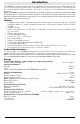


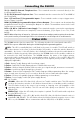
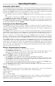
Table Of Contents
- DFTAU1114_29009079R001_3G4000_V4.0_IM_NA_ULC_UL_ENG_FRONT
- DFTAU1114_29009079R001_3G4000_V4.0_IM_NA_ULC_UL_ENG_TOC
- DFTAU1114_29009079R001_3G4000_V4.0_IM_NA_ULC_UL_ENG
- Features
- Technical Specifications
- Ratings
- Parts
- 1
- Plastic Casing
- 2
- Anchor Screw Holes (3mm)
- 3
- SIM Card Holder
- 4
- 3G Antenna
- 4A
- 3G External Antenna (Optional)*
- 5
- 3G (HSPA) Radio Module
- 6
- Antenna Connector
- 7
- Antenna Mounting Hardware
- 8
- Tamper Switch
- 9
- Status LEDs (see page 5)
- 10
- Terminal Blocks
- 11
- PC-Link Connector
- 12
- Battery Connector
- 13
- Cable Entry
- 14
- 7.2V - 2.2Ah Battery
- * Use only DSC provided antenna.
- Description
- 1. Remove the front panel.
- 2. Fit the 3G antenna [2]. Ensure the 3G antenna mounting hardware is fastened securely [3].
- 3. Attach the 3G radio module with the 3G antenna connector. Ensure that the connector is secure.
- 4. Turn on the 3G4000 and check the signal strength. 4.1 Connect the battery connector. 4.2 Connect the DC power source to +/- 12V terminals.
- 5. Allow the unit to power up.
- 6. Power down the 3G4000 by removing the DC power source and battery leads.
- 1. Using the cabinet, mark the four screw locations. Drill the anchor screw holes.
- 2. Using anchor screws (not provided), mount the cabinet to the wall.
- 3. Run the cables through the cable entry [13] or through the cabinet knockouts.
- 4. Complete the connections on the terminal blocks [11].
- 5. Reattach the front cover [1] securely to the cabinet.
- Simulated Landline Mode
- Panel Transmission Monitoring (PTM)
- Wireless Communications Sequence
- Inputs
- Outputs
- Activating the Outputs
- Swinger Shutdown
- Hardware Default
- Low Power Radio Shutdown
- Figure 2 - Wiring Diagram
- Figure 3 - Telephone Connection
- Figure 4 - Power Supply and Supervision Wiring Diagram
- Figure 5 - Fire Alarm Control Unit and 3G Transmitter
- Figure 6 - DSC Subscribers’ Unit Fire and 3G Transmitter Mounted in the Same Room
- Figure 7 - DSC Subscribers’ Unit Fire and 3G Wireless Transmitter Mounted Remotely
- Description
- Limited Warranty

Connecting the 3G4000
5
TIP (1) / RNG (2) External Telephone Line - These terminals must be connected directly to the
incoming telephone line.
T1 (3) / R1 (4) Internal Telephone Line - These
terminals must be connected to the TIP and RING of
the control panel.
Zone 1 (5) and Zone (7) Programmable Inputs -
These terminals can be set up to trigger events.
Refer to `Inputs' for details.
PGM1 (6), PGM2 (8) Programmable Open-collector Outputs - These
outputs can be activated by
programmed events. Refer to ‘Activating the Outputs’ for details. The maximum current sink of each
output must not exceed 50mA.
DC in + (9), DC in - (10) Device Power Supply -
These terminals must be connected to a rated power
supply. Once the connections are completed, connect the battery, [12] in Figure 1) to a 7.2V, 2.2Ah
battery.
Status LEDs
NOTE: When disposing of batteries, follow the instructions and precautions printed on the bat-
teries, and contact your municipal offices for information on the disposal of used batteries.
The 3G4000 interface has four status LEDs. The following describes the control panel status LEDs.
NOTE: The top two LEDs blink during the Initializing and Programming phases.
RED - This LED is normally Off; but, it will flash in the event of a trouble. This LED will switch on
within three minutes in the event of wireless Module [16] trouble, or when the wireless Network is
unavailable,
‘No Service’. If this LED flashes, the following list indicates the specific trouble based on
the number of flashes, by priority. When turned on, the 3G4000 checks for the trouble conditions to
be restored in the order listed below. The 3G4000 indicates the status of the highest priority,
unrestored trouble condition with the corresponding number of flashes of the red LED. Once the
highest priority trouble condition has been cleared, the next highest priority trouble condition is
displayed (if applicable).
1 flash -
Battery Trouble (Battery with low voltage output)
2 flashes -
Radio/SIM Trouble (Battery absent or SIM Card disconnected)
3 flashes -
Wireless Network Problem (SIM not active, poor signal strength, antenna not connected)
4 flashes -
Insufficient Signal Strength (poor location)
5 flashes -
Connect 24 Configuration SMS Trouble (Improper VRU programming. Once the configu-
ration is ready, turn off power for 2-3 seconds to allow the unit to restart and request again)
6 flashes -
Receiver not available (Improper VRU programming, receiver absent)
7 flashes -
Power Supply Trouble (DC power supply absent)
Off -
No Troubles
YELLOW - When this LED is On (solid), a Phone Line Trouble condition exists. This LED switches
on when the interface switches to the Wireless Network (due to a Landline trouble condition).
This
LED flashes slowly in the event of an incoming or outgoing voice call (regardless of the
operating status of the landline). This LED can also flash quickly once (Wireless TX) or twice
(Wireless RX).
GREEN (Top) - When this LED is On, the reception is optimal. This LED switches On only when
the other Green LED is on.
GREEN (Bottom) - If this LED is Off and the Red LED is On, the Wireless Network service is
unavailable (NO SERVICE). This LED flashes when the Wireless Network reception is poor. If this
LED
is on, the 3G4000 is able to communicate with the 3G (HSPA) or 2G (GPRS) network.