
Installation Manual

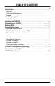
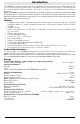


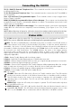
Table Of Contents
- DFTAU1114_29009079R001_3G4000_V4.0_IM_NA_ULC_UL_ENG_FRONT
- DFTAU1114_29009079R001_3G4000_V4.0_IM_NA_ULC_UL_ENG_TOC
- DFTAU1114_29009079R001_3G4000_V4.0_IM_NA_ULC_UL_ENG
- Features
- Technical Specifications
- Ratings
- Parts
- 1
- Plastic Casing
- 2
- Anchor Screw Holes (3mm)
- 3
- SIM Card Holder
- 4
- 3G Antenna
- 4A
- 3G External Antenna (Optional)*
- 5
- 3G (HSPA) Radio Module
- 6
- Antenna Connector
- 7
- Antenna Mounting Hardware
- 8
- Tamper Switch
- 9
- Status LEDs (see page 5)
- 10
- Terminal Blocks
- 11
- PC-Link Connector
- 12
- Battery Connector
- 13
- Cable Entry
- 14
- 7.2V - 2.2Ah Battery
- * Use only DSC provided antenna.
- Description
- 1. Remove the front panel.
- 2. Fit the 3G antenna [2]. Ensure the 3G antenna mounting hardware is fastened securely [3].
- 3. Attach the 3G radio module with the 3G antenna connector. Ensure that the connector is secure.
- 4. Turn on the 3G4000 and check the signal strength. 4.1 Connect the battery connector. 4.2 Connect the DC power source to +/- 12V terminals.
- 5. Allow the unit to power up.
- 6. Power down the 3G4000 by removing the DC power source and battery leads.
- 1. Using the cabinet, mark the four screw locations. Drill the anchor screw holes.
- 2. Using anchor screws (not provided), mount the cabinet to the wall.
- 3. Run the cables through the cable entry [13] or through the cabinet knockouts.
- 4. Complete the connections on the terminal blocks [11].
- 5. Reattach the front cover [1] securely to the cabinet.
- Simulated Landline Mode
- Panel Transmission Monitoring (PTM)
- Wireless Communications Sequence
- Inputs
- Outputs
- Activating the Outputs
- Swinger Shutdown
- Hardware Default
- Low Power Radio Shutdown
- Figure 2 - Wiring Diagram
- Figure 3 - Telephone Connection
- Figure 4 - Power Supply and Supervision Wiring Diagram
- Figure 5 - Fire Alarm Control Unit and 3G Transmitter
- Figure 6 - DSC Subscribers’ Unit Fire and 3G Transmitter Mounted in the Same Room
- Figure 7 - DSC Subscribers’ Unit Fire and 3G Wireless Transmitter Mounted Remotely
- Description
- Limited Warranty

Introduction
1
The 3G4000 is a wireless communicator that sends alarm system information to a Sur-Gard SG-System I,
II, III or IV Receiver through a 3G (HSPA) or 2G (GPRS) wireless network. This wireless communicator can
be used with UL/ULC Listed compatible control units, as indicated in the manufacturer's installation
instructions.
NOTE: The 3G4000 is designed to work with the Contact ID communication format as described in SIA DC-
05 Standard. Before completing the field installation of the alarm monitoring system please ensure com-
munication with the supervising central station is successful by sending several events and getting confir-
mation that they have been received.
Features
• Compatible with 4-digit or 10-digit Contact ID communication format as described in SIA DC-05
Standard. Example of suitable compatible alarm panels: DSC Models PC1864, PC1832, PC1616,
PC4020.
• Simulates landline
• Switches automatically to the 3G (HSPA) or 2G (GPRS) network in the event of landline trouble
(e.g., line down)
• Wireless Signal Indicator
• Four programmable outputs
• Contains one 12V - 1.2 Ah battery
• Case Tamper Output
• Landline overvoltage protection
• Tri-band UMTS/HSPA; Quad-Band GSM/EDGE Radio
• Four programmable inputs
• 3G (HSPA)/2G (GPRS) / Internet communication with Sur-Gard SG-SystemI/II/III/IV
• Panel transmission monitoring for up to four phone numbers
Technical Specifications
The input voltage to the 3G4000 can be drawn from the UL/ULC Listed control panel or provided by an
external UL/ULC Listed power supply rated for the application (external power-limited source).
NOTE: The power supply must be Class 2, Power Limited. For residential applications a suitable power adap-
tor is model DSC ADP1310-NAU (for USA) and model DSC ADP1310-NA (for Canada).
Ratings
Power Supply Ratings - Input Voltage (for long-term operation)
JP3-OFF with internal battery: ...........................13.7V
DC required
Current Consumption
Average: ...........................................120mA*
Peak: .............................................700mA*
* Plus any current drawn from the 3G4000 AUX+ terminal
Working Voltage Range ...................................7.2VDC
Battery: ...................................NiMH, rated 7.2V, 2.2Ah
Battery charging voltage: .....................................
7VDC
Battery charging current: ....................................150mA
NOTE: Battery must be replaced every 3-5 years.
Operating frequency: .................................850/1900MHz
Antenna gain: .........................................2.0dBi
Environmental Specifications
Operating temperature: ............................0°C-49°C
(32°F-120°F)
Humidity: ............................93%RH
Maximum (non-condensing)
Mechanical Specifications
Dimensions (plastic enclosure, painted): ......125mm
× 220mm × 22mm / 4.8” × 4” × 0.875”
Weight (without battery): ................................400g
/ 1.2oz
Simulated Telco Loop specifications (TIP/RING)
On-Hook Voltage: .......................................
35VDC
Loop Current .......................................... 25mA
Loop Resistance ......................................
600Ohms