
Installation Manual
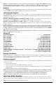
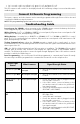

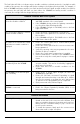

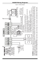


Table Of Contents
- DFTAU1114_29009079R001_3G4000_V4.0_IM_NA_ULC_UL_ENG_FRONT
- DFTAU1114_29009079R001_3G4000_V4.0_IM_NA_ULC_UL_ENG_TOC
- DFTAU1114_29009079R001_3G4000_V4.0_IM_NA_ULC_UL_ENG
- Features
- Technical Specifications
- Ratings
- Parts
- 1
- Plastic Casing
- 2
- Anchor Screw Holes (3mm)
- 3
- SIM Card Holder
- 4
- 3G Antenna
- 4A
- 3G External Antenna (Optional)*
- 5
- 3G (HSPA) Radio Module
- 6
- Antenna Connector
- 7
- Antenna Mounting Hardware
- 8
- Tamper Switch
- 9
- Status LEDs (see page 5)
- 10
- Terminal Blocks
- 11
- PC-Link Connector
- 12
- Battery Connector
- 13
- Cable Entry
- 14
- 7.2V - 2.2Ah Battery
- * Use only DSC provided antenna.
- Description
- 1. Remove the front panel.
- 2. Fit the 3G antenna [2]. Ensure the 3G antenna mounting hardware is fastened securely [3].
- 3. Attach the 3G radio module with the 3G antenna connector. Ensure that the connector is secure.
- 4. Turn on the 3G4000 and check the signal strength. 4.1 Connect the battery connector. 4.2 Connect the DC power source to +/- 12V terminals.
- 5. Allow the unit to power up.
- 6. Power down the 3G4000 by removing the DC power source and battery leads.
- 1. Using the cabinet, mark the four screw locations. Drill the anchor screw holes.
- 2. Using anchor screws (not provided), mount the cabinet to the wall.
- 3. Run the cables through the cable entry [13] or through the cabinet knockouts.
- 4. Complete the connections on the terminal blocks [11].
- 5. Reattach the front cover [1] securely to the cabinet.
- Simulated Landline Mode
- Panel Transmission Monitoring (PTM)
- Wireless Communications Sequence
- Inputs
- Outputs
- Activating the Outputs
- Swinger Shutdown
- Hardware Default
- Low Power Radio Shutdown
- Figure 2 - Wiring Diagram
- Figure 3 - Telephone Connection
- Figure 4 - Power Supply and Supervision Wiring Diagram
- Figure 5 - Fire Alarm Control Unit and 3G Transmitter
- Figure 6 - DSC Subscribers’ Unit Fire and 3G Transmitter Mounted in the Same Room
- Figure 7 - DSC Subscribers’ Unit Fire and 3G Wireless Transmitter Mounted Remotely
- Description
- Limited Warranty

3G4000 Wiring Diagrams
14
Figure 5 - Fire Alarm Control Unit and 3G Transmitter
AUX Power
(12V/700mA)
RM1C ULC
Relay
Fire Alarm
Control Unit
TIP/RING
Zone Input
Outputs
Fire
Trouble
3G Wireless
Transmitter
3G4000
T1/R1
TIP/RING
Zone PGM2
Inputs Output
3G4000 cabinet
3G (HSPA) or
2G (GPRS)
AC Input
NOTES:
- Power for 3G4000 shall be provided from Fire
Alarm Control Unit or separately Listed power supply
rated for the application, 12V/700mA (Jumper JP3
shall be set to on for Fire Monitoring).
- All wiring connections must be run in a protective
conduit.
- For local supervision of
the wireless transmitter connect
PGM output from 3G4000 to one zone input on the
Fire Alarm Control Unit.
- Dry Contact Trouble output from ULC Listed Fire
Alarm Control Unit must be connected to zone input
on the 3G4000 for supervision of Tip/Ring connection.
- Fire Alarms must be sent over both communication
channels. Fire output from Fire Alarm Control Unit
must be connected to the Input 1 on the 3G4000.
- 24h Test Transmission must be enabled on the dialler
and on the 3G4000.
PSTN
Figure 6 - DSC Subscribers’ Unit Fire and 3G Transmitter Mounted in the Same Room
(y)
Fire Alarm
Control Unit
Outputs
Fire
Supervisory
Trouble
DSC
Subscribers’
Unit Fire
Zone
Inputs
TIP
TIP RING
PGM1
DSC Keypad
LCD4501
PK55XX
3G Wireless
Transmitter
3G4000
T1/R1
TIP/RING
Zone
Input PGM2
AUX Power
12V/700mA
RM1C ULC
Relay
PC5003C
PC4050CR
cabine
t
3G (HSPA)/2G (GPRS)
PSTN
AC Input
AC Input
NOTES:
- Power for 3G4000 must be provided from Fire
Alarm Control Unit or separately listed power
supply rated for the application (12V/700mA)
(Jumper JP3 shall be on for Fire Monitoring).
- All wiring connections must be run in a protective conduit.
- Phone Line Monitoring (TLM) must be enabled.
- Connect PGM4 output from 3G4000 (Trouble
Conditions) to a zone input on the Subscriber Unit
for supervision of the GSM Transmitter.
- 24hr Test Transmission over phone line (PSTN) and
3G4000 must be enabled.
- Fire Alarms must be sent over both communication
channels.
- On the Subscribers’ Unit, program PGM1 for
PC1616/PC1832/PC1864 as System Event (Section
[009] as type 10; Section [501] Fire Event option 2
ON). An alternate option is to program PGM1 as Zone
Follower (Sec [009] = 29) and assign Fire Zone to PGM1
in Section [551]. Ensure Bit 3 is on in [501]. In this case,
a restored fire alarm condition does not require the DSC
control panel to be reset.
For PC4020 program PGM1 as type 49 Steady Fire ([00070049]).
- Dry contact outputs from ULC Listed Fire Alarm
Control Unit must be connected to zone inputs on
the ULC Listed DSC Subscribers’ Unit Fire.
PC4020
PC1864
PC1832
PC1616
RM1C ULC
Relay
3G4000 cabinet
- Phone Line trouble is indicated by Yellow LED on 3G4000.
- Refer to detailed diagrams in Figure 7.