
Installation Manual
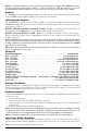
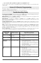

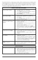

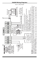


Table Of Contents
- DFTAU1114_29009079R001_3G4000_V4.0_IM_NA_ULC_UL_ENG_FRONT
- DFTAU1114_29009079R001_3G4000_V4.0_IM_NA_ULC_UL_ENG_TOC
- DFTAU1114_29009079R001_3G4000_V4.0_IM_NA_ULC_UL_ENG
- Features
- Technical Specifications
- Ratings
- Parts
- 1
- Plastic Casing
- 2
- Anchor Screw Holes (3mm)
- 3
- SIM Card Holder
- 4
- 3G Antenna
- 4A
- 3G External Antenna (Optional)*
- 5
- 3G (HSPA) Radio Module
- 6
- Antenna Connector
- 7
- Antenna Mounting Hardware
- 8
- Tamper Switch
- 9
- Status LEDs (see page 5)
- 10
- Terminal Blocks
- 11
- PC-Link Connector
- 12
- Battery Connector
- 13
- Cable Entry
- 14
- 7.2V - 2.2Ah Battery
- * Use only DSC provided antenna.
- Description
- 1. Remove the front panel.
- 2. Fit the 3G antenna [2]. Ensure the 3G antenna mounting hardware is fastened securely [3].
- 3. Attach the 3G radio module with the 3G antenna connector. Ensure that the connector is secure.
- 4. Turn on the 3G4000 and check the signal strength. 4.1 Connect the battery connector. 4.2 Connect the DC power source to +/- 12V terminals.
- 5. Allow the unit to power up.
- 6. Power down the 3G4000 by removing the DC power source and battery leads.
- 1. Using the cabinet, mark the four screw locations. Drill the anchor screw holes.
- 2. Using anchor screws (not provided), mount the cabinet to the wall.
- 3. Run the cables through the cable entry [13] or through the cabinet knockouts.
- 4. Complete the connections on the terminal blocks [11].
- 5. Reattach the front cover [1] securely to the cabinet.
- Simulated Landline Mode
- Panel Transmission Monitoring (PTM)
- Wireless Communications Sequence
- Inputs
- Outputs
- Activating the Outputs
- Swinger Shutdown
- Hardware Default
- Low Power Radio Shutdown
- Figure 2 - Wiring Diagram
- Figure 3 - Telephone Connection
- Figure 4 - Power Supply and Supervision Wiring Diagram
- Figure 5 - Fire Alarm Control Unit and 3G Transmitter
- Figure 6 - DSC Subscribers’ Unit Fire and 3G Transmitter Mounted in the Same Room
- Figure 7 - DSC Subscribers’ Unit Fire and 3G Wireless Transmitter Mounted Remotely
- Description
- Limited Warranty

3G4000 Wiring Diagrams
12
Figure 2 - Wiring Diagram
1K5
Battery not required
if JP3 is ON
9-14V
DC
/ *700mA (max)
Supervision
Relay
Optional
use of PGM
output (See
Programming)
WARNING:
Incorrect connections may result in PTC failure or improper operation. Inspect wiring and ensure connections are correct before turning on.
All circuits are classified for UL installations as Power Limited/Class II Power Limited. Do not route any wiring over circuit boards. Maintain at least 1”
(25.4mm) separation. A minimum 1/4” (6.4mm) separation must be maintained at all points between Power Limited wiring and all other Non-Power Limited
wiring. Route wires as indicated in the diagram.
NOTE: For ULC Commercial Burglary Installation requirements please refer to Figures 5, 6, 7 and to the ULC Installation Guide P/N 29002157.
Telephone Line
Connection
RJ-45
Examples of Control Units/Subscribers Units or Power Supplies compatible
models: DSC PC1864, PC1832, PC1616, PC5204, etc.
Electrical Ratings: 13.7 VDC / 700 mA
Power Supply: COM BURG, use listed control panel; RES FIRE/BURG,
use ADP1320-NAU/NA (US/CDN) and Battery: 7.2V/2.2Ah
For use in dry indoor ordinary locations only. For installation refer to NFPA70, 72.
Alarm Control Panel with
Dialler Interface
(Supports Contact ID and
SIA formats)
BATTERY
Sealed
Rechargeable
7.2V / 2.2Ah
RM1-UL Installations
RM1C-ULC Installations
Connect relay contacts to a zone input on the alarm control
panel for 3G4000 troubles supervision (24hr-type zone)
T
I
P
R
I
N
G
Panel Aux Power or
External Power Supply
(13.8V
DC
required for
normal, long-term operation)
Typical battery charge: 30-50 mA
Recommended Model: 12V/1.2Ah
3G4000
TIP
RING
T1
R1
Z1
PGM1
Z2
PGM2
DC IN
+
-
1
2
3
4
5
6
7
9
8
10
WARNING!
HIGH VOLTAGE.
DISCONNECT DC
POWER AND
TELEPHONE LINES
PRIOR TO SERVICING.
Incorrect connections
may result in failure
or improper operation.
}
Inputs to be connected
to dry contact outputs
from alarm control panel
(Use No. 26 AWG
wires for the
connection to PSTN)