
Installation Manual
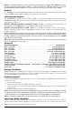
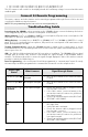

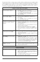

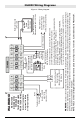


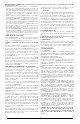
Table Of Contents
- DFTAU1114_29009079R001_3G4000_V4.0_IM_NA_ULC_UL_ENG_FRONT
- DFTAU1114_29009079R001_3G4000_V4.0_IM_NA_ULC_UL_ENG_TOC
- DFTAU1114_29009079R001_3G4000_V4.0_IM_NA_ULC_UL_ENG
- Features
- Technical Specifications
- Ratings
- Parts
- 1
- Plastic Casing
- 2
- Anchor Screw Holes (3mm)
- 3
- SIM Card Holder
- 4
- 3G Antenna
- 4A
- 3G External Antenna (Optional)*
- 5
- 3G (HSPA) Radio Module
- 6
- Antenna Connector
- 7
- Antenna Mounting Hardware
- 8
- Tamper Switch
- 9
- Status LEDs (see page 5)
- 10
- Terminal Blocks
- 11
- PC-Link Connector
- 12
- Battery Connector
- 13
- Cable Entry
- 14
- 7.2V - 2.2Ah Battery
- * Use only DSC provided antenna.
- Description
- 1. Remove the front panel.
- 2. Fit the 3G antenna [2]. Ensure the 3G antenna mounting hardware is fastened securely [3].
- 3. Attach the 3G radio module with the 3G antenna connector. Ensure that the connector is secure.
- 4. Turn on the 3G4000 and check the signal strength. 4.1 Connect the battery connector. 4.2 Connect the DC power source to +/- 12V terminals.
- 5. Allow the unit to power up.
- 6. Power down the 3G4000 by removing the DC power source and battery leads.
- 1. Using the cabinet, mark the four screw locations. Drill the anchor screw holes.
- 2. Using anchor screws (not provided), mount the cabinet to the wall.
- 3. Run the cables through the cable entry [13] or through the cabinet knockouts.
- 4. Complete the connections on the terminal blocks [11].
- 5. Reattach the front cover [1] securely to the cabinet.
- Simulated Landline Mode
- Panel Transmission Monitoring (PTM)
- Wireless Communications Sequence
- Inputs
- Outputs
- Activating the Outputs
- Swinger Shutdown
- Hardware Default
- Low Power Radio Shutdown
- Figure 2 - Wiring Diagram
- Figure 3 - Telephone Connection
- Figure 4 - Power Supply and Supervision Wiring Diagram
- Figure 5 - Fire Alarm Control Unit and 3G Transmitter
- Figure 6 - DSC Subscribers’ Unit Fire and 3G Transmitter Mounted in the Same Room
- Figure 7 - DSC Subscribers’ Unit Fire and 3G Wireless Transmitter Mounted Remotely
- Description
- Limited Warranty

10
The Red light will flash to indicate various trouble conditions outlined previously. If multiple trouble
conditions are present, the red light will flash according to the highest priority trouble. For example, if
both a 3G4000 low battery trouble (one flash) and an insufficient signal strength trouble (four flashes)
are present; the red light will flash one time. Once the 3G4000 low battery trouble condition is
corrected, the red light will then begin flashing four times.
General Troubles With Your System
The control panel is displaying a tele-
phone line trouble condition
• Ensure T1 and R1 of the 3G4000 are wired to the TIP
and RING terminals of the control panel.
• If the 3G4000 is being used as the primary communica-
tor, the yellow light will always be ON.
• If the 3G4000 red light is FLASHING, refer to the Red
Light Status Chart.
The control panel displays a commu-
nication trouble condition
• Ensure the panel is programmed for Contact ID.
• Ensure the control panel does not indicate a TLM trou-
ble condition.
• If the 3G4000 red light is FLASHING refer to the Red
Light Status chart in this guide.
No signals are received at the central
station but no trouble condition is
displayed
• Ensure the control panel has a central station phone
number
programmed.
• Ensure the control panel has the correct account num-
ber programmed.
• Verify the reporting codes are programmed or the auto
Contact ID option is enabled.
• Ensure the control panel communicator is enabled.
• Connect a handset to T1 and R1 of the 3G4000 in mon-
itor mode to verify the control panel is trying to commu-
nicate.
Not receiving internal signals gener-
ated directly from the 3G4000
• Ensure the 3G4000 was initialized with the correct
account number. This can be checked by logging into
the Connect 24 website.
• Ensure that there are no trouble conditions on the
3G4000.
The 3G4000 Yellow and Red lights
flash constantly
• Ensure there is good signal strength (at least one
3G4000 green light ON).
• Ensure the SIM card is activated. Depending on signal
strength and network activity it can take up to 10 min-
utes for the network to program the unit; wait at least
15 minutes for the programming to be completed.
• Cycle power and verify SIM and signal.
The phone line is seized when the
3G4000 is connected
• Verify correct phone line wiring.
• Ensure the Ringer Equivalency Number (REN) is not
being exceeded on the line.
General Information
Removing/Connecting the antenna • To remove the antenna from the 3G4000, place your
thumb on the end of the connector at the modem, then
place a screwdriver between the modem and connector.
Gently turn the screwdriver away to ‘pop’ out the con-
nector from the modem.
• To install the antenna, firmly push the connector into
the modem until it ‘snaps’ into place.