
Installation Manual
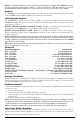
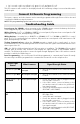

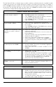

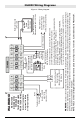


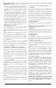
Table Of Contents
- DFTAU1114_29009079R001_3G4000_V4.0_IM_NA_ULC_UL_ENG_FRONT
- DFTAU1114_29009079R001_3G4000_V4.0_IM_NA_ULC_UL_ENG_TOC
- DFTAU1114_29009079R001_3G4000_V4.0_IM_NA_ULC_UL_ENG
- Features
- Technical Specifications
- Ratings
- Parts
- 1
- Plastic Casing
- 2
- Anchor Screw Holes (3mm)
- 3
- SIM Card Holder
- 4
- 3G Antenna
- 4A
- 3G External Antenna (Optional)*
- 5
- 3G (HSPA) Radio Module
- 6
- Antenna Connector
- 7
- Antenna Mounting Hardware
- 8
- Tamper Switch
- 9
- Status LEDs (see page 5)
- 10
- Terminal Blocks
- 11
- PC-Link Connector
- 12
- Battery Connector
- 13
- Cable Entry
- 14
- 7.2V - 2.2Ah Battery
- * Use only DSC provided antenna.
- Description
- 1. Remove the front panel.
- 2. Fit the 3G antenna [2]. Ensure the 3G antenna mounting hardware is fastened securely [3].
- 3. Attach the 3G radio module with the 3G antenna connector. Ensure that the connector is secure.
- 4. Turn on the 3G4000 and check the signal strength. 4.1 Connect the battery connector. 4.2 Connect the DC power source to +/- 12V terminals.
- 5. Allow the unit to power up.
- 6. Power down the 3G4000 by removing the DC power source and battery leads.
- 1. Using the cabinet, mark the four screw locations. Drill the anchor screw holes.
- 2. Using anchor screws (not provided), mount the cabinet to the wall.
- 3. Run the cables through the cable entry [13] or through the cabinet knockouts.
- 4. Complete the connections on the terminal blocks [11].
- 5. Reattach the front cover [1] securely to the cabinet.
- Simulated Landline Mode
- Panel Transmission Monitoring (PTM)
- Wireless Communications Sequence
- Inputs
- Outputs
- Activating the Outputs
- Swinger Shutdown
- Hardware Default
- Low Power Radio Shutdown
- Figure 2 - Wiring Diagram
- Figure 3 - Telephone Connection
- Figure 4 - Power Supply and Supervision Wiring Diagram
- Figure 5 - Fire Alarm Control Unit and 3G Transmitter
- Figure 6 - DSC Subscribers’ Unit Fire and 3G Transmitter Mounted in the Same Room
- Figure 7 - DSC Subscribers’ Unit Fire and 3G Wireless Transmitter Mounted Remotely
- Description
- Limited Warranty

Yellow Light
Status
What It Means: Wireless Communicator Status/Communication
Indicator
Blue Light ON • When used as the primary communicator, the yellow light will always be
ON.
• When used as a backup communicator, the yellow light will be ON when
there is a no phone line connected to the 3G4000 TIP and RING, or the line
voltage goes below 2.8VDC.
Blue Light OFF • Indicates a good phone line is connected to the 3G4000. (more than 2.8
VDC detected across the 3G4000 TIP and RING terminals).
Blue Light
FLASHING
• The yellow light will flash one time when the 3G4000 transmits a signal
and two times when a kissoff is received.
Red Light
Status
What it means:
Trouble Status
Trouble Status - Troubleshooting Steps
One Flash 3G4000 Low Battery • Measure the battery under load and verify it is
charged to at least 12.5 VDC. If not, wait at least 1
hour for the battery to charge.
• Remove the battery and measure the voltage across
the two battery leads; the voltage should be at least
13.5 VDC.
• Verify the input DC supply is rated at 13.8VDC @
120mA minimum.
• Ensure the 3G4000 jumper J3 is OFF.
Two Flashes SIM/Radio Trouble • Ensure the SIM Card is inserted correctly and firmly.
• Ensure the antenna cable is plugged securely into the
radio connector.
• Ensure the power source connected to the 3G4000 is
providing 13.8VDC @ 120mA and that the battery is
fully charged.
Three
Flashes
Wireless Network Prob-
lem
• Ensure the SIM card has been activated.
• The antenna cable should be plugged securely into
the radio connector.
• Ensure there is good signal strength (at least one
green light ON).
• Verify the installation area is not experiencing a net-
work outage.
Four Flashes Insufficient Signal
Strength
• Ensure there is good signal strength (at least one
3G4000 green light ON).
• Ensure the antenna cable is plugged securely into the
radio connector.
Five Flashes Configuration Trouble • Ensure the SIM card is activated.
Six Flashes Receiver Not Available • Contact the monitoring station to verify that the
3G4000 programming is correct (port, IP address,
DNIS).
• Contact your central station to verify they are not
experiencing any receiver issues.
Seven
Flashes
DC Supply Trouble • Ensure the power source connected to the 3G4000 is
providing 13.8VDC @ 120mA.
9