
Installation Manual
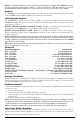
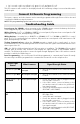

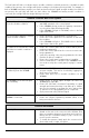

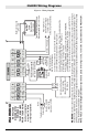


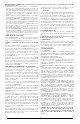
Table Of Contents
- DFTAU1114_29009079R001_3G4000_V4.0_IM_NA_ULC_UL_ENG_FRONT
- DFTAU1114_29009079R001_3G4000_V4.0_IM_NA_ULC_UL_ENG_TOC
- DFTAU1114_29009079R001_3G4000_V4.0_IM_NA_ULC_UL_ENG
- Features
- Technical Specifications
- Ratings
- Parts
- 1
- Plastic Casing
- 2
- Anchor Screw Holes (3mm)
- 3
- SIM Card Holder
- 4
- 3G Antenna
- 4A
- 3G External Antenna (Optional)*
- 5
- 3G (HSPA) Radio Module
- 6
- Antenna Connector
- 7
- Antenna Mounting Hardware
- 8
- Tamper Switch
- 9
- Status LEDs (see page 5)
- 10
- Terminal Blocks
- 11
- PC-Link Connector
- 12
- Battery Connector
- 13
- Cable Entry
- 14
- 7.2V - 2.2Ah Battery
- * Use only DSC provided antenna.
- Description
- 1. Remove the front panel.
- 2. Fit the 3G antenna [2]. Ensure the 3G antenna mounting hardware is fastened securely [3].
- 3. Attach the 3G radio module with the 3G antenna connector. Ensure that the connector is secure.
- 4. Turn on the 3G4000 and check the signal strength. 4.1 Connect the battery connector. 4.2 Connect the DC power source to +/- 12V terminals.
- 5. Allow the unit to power up.
- 6. Power down the 3G4000 by removing the DC power source and battery leads.
- 1. Using the cabinet, mark the four screw locations. Drill the anchor screw holes.
- 2. Using anchor screws (not provided), mount the cabinet to the wall.
- 3. Run the cables through the cable entry [13] or through the cabinet knockouts.
- 4. Complete the connections on the terminal blocks [11].
- 5. Reattach the front cover [1] securely to the cabinet.
- Simulated Landline Mode
- Panel Transmission Monitoring (PTM)
- Wireless Communications Sequence
- Inputs
- Outputs
- Activating the Outputs
- Swinger Shutdown
- Hardware Default
- Low Power Radio Shutdown
- Figure 2 - Wiring Diagram
- Figure 3 - Telephone Connection
- Figure 4 - Power Supply and Supervision Wiring Diagram
- Figure 5 - Fire Alarm Control Unit and 3G Transmitter
- Figure 6 - DSC Subscribers’ Unit Fire and 3G Transmitter Mounted in the Same Room
- Figure 7 - DSC Subscribers’ Unit Fire and 3G Wireless Transmitter Mounted Remotely
- Description
- Limited Warranty

8
• for 1 second -- red is on, yellow is off, green 1 is off, and green 2 is off.
• for 1 second -- red is off, yellow is on, green 1 is on, and green 2 is on.
This LED sequence will continue to be displayed until the low battery voltage is restored and the radio
enabled again.
Connect 24 Remote Programming
The inputs, outputs, and other features can be remotely programmed through Connect 24 for fast and
convenient installation using the internet.
Troubleshooting Guide
NOTE: This programming option has not been investigated by UL.
Powering up the 3G4000 – when powering up the 3G4000, always connect the battery first before
connecting primary DC power from the control panel or transformer.
Wiring Primary –
R-1/T-1 of 3G4000 to RING/TIP of control panel, DC power from control panel or DC
transformer to DC input, backup battery if JP3 OFF.
Wiring Backup –
Incoming line to RING/TIP on 3G4000, R-1/T-1 of 3G4000 to RING/TIP of control
panel, R-1/T-1 of control panel to house phones, DC power from control panel or DC transformer to DC
input, backup battery if JP3 OFF.
Testing Communications –
when the 3G4000 transmits a signal for the control panel, or for an
internal transmission, the YELLOW light will flash one time when the signal is transmitted and two times
when it gets a kiss-off.
SIM –
the SIM should be activated at least 24 hours prior to installation. The 3G4000 will show signal
strength with an inactive SIM, however it will display the signal strength of any available wireless
network. The SIM must be active to ensure the signal strength displayed is that of the wireless network
provider for which the SIM belongs to.
Panel Programming –
the control panel should be programmed to communicate Contact ID exactly
the same way it would be programmed to communicate Contact ID over the telephone line.
Green Light
Status
What it means: Signal Strength Status
Both Green Lights ON
Excellent Signal
Strength
• Unit can be installed in the current mounting
location.
One Green Light ON
Good Signal Strength
• Unit can be installed in the current mounting
location.
Bottom Green Light
FLASHING
Poor Signal Strength
• Ensure the antenna cable is plugged securely
into the radio connector.
• If the SIM is active, connect a battery to the
unit and test various locations for good/excel-
lent signal strength.
• Connect an antenna extension kit (GS-15ANT,
GS-25ANT or GS-50ANT).
Both Green Lights
OFF
No Signal Strength
• If the red light is also FLASHING, refer to the
RED light chart.
• Verify SIM card is activated.
• Ensure the antenna cable is plugged securely
into the radio connector.
• If the SIM is active, connect a battery to the
unit and test various locations for good/excel-
lent signal strength.
• Connect an antenna extension kit (GS-15ANT,
GS-25ANT or GS-50ANT).