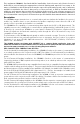
3G4000 3G (HSPA) WIRELESS ALARM COMMUNICATOR INSTALLATION MANUAL V4.0 WARNING: This manual contains information on limitations regarding product use and function and information on the limitations as to liability of the manufacturer. The entire manual should be carefully read.
TABLE OF CONTENTS Introduction . . . . . . . . . . . . . . . . . . . . . . . . . . . . . . . . . . . . . . . . . . . . .1 Features . . . . . . . . . . . . . . . . . . . . . . . . . . . . . . . . . . . . . . . . . . . . . . . .1 Technical Specifications . . . . . . . . . . . . . . . . . . . . . . . . . . . . . . . . . . .1 Ratings . . . . . . . . . . . . . . . . . . . . . . . . . . . . . . . . . . . . . . . . . . . . . . . . .1 Identification of Parts . . . . . . . . . . . . . . . . . . . . . . . . . . . . .
IMPORTANT The equipment is fixed, wall-mounted and shall be installed in the position specified in these instructions. The equipment enclosure must be fully assembled and closed, with all the necessary screws/tabs and secured to a wall before operation.
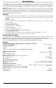
Introduction The 3G4000 is a wireless communicator that sends alarm system information to a Sur-Gard SG-System I, II, III or IV Receiver through a 3G (HSPA) or 2G (GPRS) wireless network. This wireless communicator can be used with UL/ULC Listed compatible control units, as indicated in the manufacturer's installation instructions. NOTE: The 3G4000 is designed to work with the Contact ID communication format as described in SIA DC05 Standard.
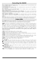
Identification of Parts Figure 1 - Parts 4A 1 2 3 M 7 4 5 6 ANT1 SERIAL NUMBER 1000X500 UA 674 JK1 REV02 INHIB IT AR E A R OUT R OUT AR E A T H3 2 INHIB IT T H2 F IDB 2 OPEN OPEN C 97 C ON5 C 96 C 95 R OU T IN H IB IT C 94 AR E A F IDB 1 8 SW1 9 P C L INK C ON2 SI + F IDB 4 C ON1 NOTE: For UL/ULC installations, connections between the alarm control panel outputs (telephone interface Tip/Ring, output relay contacts) and 3G4000 inputs (Tip/Ring, Z1-Z4) shall (TIP/RING/Z1
This equipment 3G4000 is fixed and shall be installed by Service Persons only (Service Person is defined as a person having the appropriate technical training and experience necessary to be aware of hazards to which that person may be exposed in performing a task, and of measures available to minimize the risks to that person or other persons). It shall be installed and used within an environment that provides the pollution degree max 2, over voltages category II, in non-hazardous, indoor locations only.
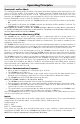
Installing the 3G4000 CONNECT 24 Enrolment Information Only authorized dealers can enrol a 3G4000 with CONNECT 24. Dealer application forms and additional information on the CONNECT 24 Voice Response Unit (VRU) can be found at the CONNECT 24 website www.connect24.com. Please contact CONNECT 24 at the number below for assistance: USA 1-888-251-7458 CANADA 1-888-955-5583 NOTE: Step 1 should be performed before turning on the 3G4000 unit.
Connecting the 3G4000 TIP (1) / RNG (2) External Telephone Line - These terminals must be connected directly to the incoming telephone line. T1 (3) / R1 (4) Internal Telephone Line - These terminals must be connected to the TIP and RING of the control panel. Zone 1 (5) and Zone (7) Programmable Inputs - These terminals can be set up to trigger events. Refer to `Inputs' for details. PGM1 (6), PGM2 (8) Programmable Open-collector Outputs - These outputs can be activated by programmed events.
Operating Principles Simulated Landline Mode The simulated landline provides the alarm control panel (with dialer interface) with a back up line in the event of PSTN line trouble. If the voltage on the landline terminals (TIP/RNG) drops below 2.8V for a period of between 10 seconds and 45 seconds - depending on the device connected to the T1/R1 terminals- the 3G4000 switches the connected telephone device to the wireless network.
NOTE: For UL/ULC installations, connections between alarm panel outputs and 3G4000 inputs must be run in protective mechanical conduits. To reduce interference with the antenna, it is recommended that the metal conduit is not connected to the knock-outs in the top of the cabinet. Outputs The 3G4000 has four programmable outputs to activate in response to the associated events. Refer to the 3G4000 Wiring Diagram (Figure 2) at the back of this manual.
• for 1 second -- red is on, yellow is off, green 1 is off, and green 2 is off. • for 1 second -- red is off, yellow is on, green 1 is on, and green 2 is on. This LED sequence will continue to be displayed until the low battery voltage is restored and the radio enabled again. Connect 24 Remote Programming The inputs, outputs, and other features can be remotely programmed through Connect 24 for fast and convenient installation using the internet.
Yellow Light Status What It Means: Wireless Communicator Status/Communication Indicator Blue Light ON • When used as the primary communicator, the yellow light will always be ON. • When used as a backup communicator, the yellow light will be ON when there is a no phone line connected to the 3G4000 TIP and RING, or the line voltage goes below 2.8VDC. Blue Light OFF • Indicates a good phone line is connected to the 3G4000. (more than 2.8 VDC detected across the 3G4000 TIP and RING terminals).
The Red light will flash to indicate various trouble conditions outlined previously. If multiple trouble conditions are present, the red light will flash according to the highest priority trouble. For example, if both a 3G4000 low battery trouble (one flash) and an insufficient signal strength trouble (four flashes) are present; the red light will flash one time. Once the 3G4000 low battery trouble condition is corrected, the red light will then begin flashing four times.
General Information Enrolling a 3G4000 • The 3G4000 can be enrolled by going through the GVRU voice prompt, and completing the activation of the SIM card, and the initialization of the 3G4000. • The 3G4000 can also be enrolled using the Connect 24 website (www.connect24.com). SIM card activation period • A SIM card can take up to 24 hours to be activated by the provider. However, it typically takes less than an hour for the SIM card to be activated. Checking SIM status • Go to www.connect24.
Z1 PGM1 R1 T1 6 5 4 3 8 Z2 PGM2 7 Optional use of PGM output (See Programming) 1K5 Inputs to be connected to dry contact outputs from alarm control panel + DC IN - 9 10 Typical battery charge: 30-50 mA Recommended Model: 12V/1.2Ah BATTERY Sealed Rechargeable 7.2V / 2.2Ah Battery not required if JP3 is ON (Use No. 26 AWG wires for the connection to PSTN) Panel Aux Power or External Power Supply Supervision 9-14VDC/ *700mA (max) (13.
3G4000 Wiring Diagrams Figure 3 - Telephone Connection CONTROL PANEL RJ-31X Incoming Phone line Handset RING RI TIP 8 9 10 RI TI TIP RING TI GRAY (R) TIP RING 2 BROWN (T) GREEN (T) RED (R) 1 3 4 5 6 T1 R1 Z1 PGM1 7 Z2 PGM2 + DC IN - 3G4000 Figure 4 - Power Supply and Supervision Wiring Diagram NOTES 1. Program the Zone/Point as “Supervisory” type with keypad only annunciation when in Alarm. Do NOT use a point that is normally used for 2-Wire Smoke detectors.
3G4000 Wiring Diagrams Figure 5 - Fire Alarm Control Unit and 3G Transmitter Fire Alarm Control Unit AUX Power (12V/700mA) 3G Wireless Transmitter 3G (HSPA) or 2G (GPRS) 3G4000 TIP/RING T1/R1 TIP/RING PSTN Zone Input Zone Inputs Outputs Fire Trouble PGM2 Output RM1C ULC Relay 3G4000 cabinet AC Input NOTES: - Power for 3G4000 shall be provided from Fire Alarm Control Unit or separately Listed power supply rated for the application, 12V/700mA (Jumper JP3 shall be set to on for Fire Monitoring).
3G4000 Wiring Diagrams Figure 7 - DSC Subscribers’ Unit Mounted Remotely y Fire andg3G Wireless Transmitter p y Fire Alarm Control Unit DSC Subscribers’ Unit Fire Outputs Fire Supervisory Trouble Zone Inputs AUX Power 12V/700mA PSTN T1/R1 Zone Input TIP/RING PGM1 PGM2 PGM1 RM1C ULC Relay RM1C ULC Relay RM1C ULC Relay PC5003C PC4050CR cabinet AC Input 3G (HSPA)/2G (GPRS) 3G4000 TIP RING PC4020 PC1864 PC1832 PC1616 3G Wireless Transmitter AC Input DSC Keypad LCD4501 PK55XX GS30XX cabinet
IMPORTANT READ CAREFULLY: DSC Software purchased with or without Products and Components is copyrighted and is purchased under the following license terms: • This End User License Agreement ("EULA") is a legal agreement between You (the company, individual or entity who acquired the Software and any related Hardware) and Digital Security Controls, a division of Tyco Safety Products Canada Ltd.
MODIFICATION STATEMENT Digital Security Controls has not approved any changes or modifications to this device by the user. Any changes or modifications could void the user’s authority to operate the equipment. Digital Security Controls n’approuve aucune modification apportée à l’appareil par l’utilisateur, quelle qu’en soit la nature. Tout changement ou modification peuvent annuler le droit d’utilisation de l’appareil par l’utilisateur.
Limited Warranty Digital Security Controls warrants the original purchaser that for a period of twelve months from the date of purchase, the product shall be free of defects in materials and workmanship under normal use. During the warranty period, Digital Security Controls shall, at its option, repair or replace any defective product upon return of the product to its factory, at no charge for labour and materials.