
User's Manual


3G Alarm Communicator Installlation Manual Yellow Trouble LED
9
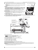
5. Alternately, you can reposition the Panel to improve signal strength. Dismount the panel and move it to another location to achieve the required signal
strength. If the Panel is relocated to improve signal strength, mount it in the new location.
6. When final Panel/antenna location is determined, continue at the Initial Panel Programmingsection.
The Communicator has 4 onboard LED indicators. These include 1 yellow trouble LED, 1 red Network Connection Status LED, and 2 green Signal Strength
LEDs. The LED meaning is described in this Section.
Yellow Trouble LED
This yellow LED will flash to indicate a trouble on the unit. The number of flashes indicates the type of trouble. See the table below for the coded flashes and
the conditions which will activate the Trouble Status LED.
NOTE: Only the highest priority trouble (2 Flashes is the highest priority trouble) is indicated. When this trouble is restored, the next highest trouble will indi-
cate, if present. This will continue until all troubles have been cleared. (yellow LED is not flashing).
The following paragraphs describe the conditions associated with the trouble indicated:
Panel Supervision Trouble (2 Flashes)
This trouble will be indicated when communication between the Communicator module and the Panel fails. If the module can not communicate with the Panel
(e.g., loss of power to the panel) the Communicator will send the ‘Panel Absent Trouble Event’ message to the central station receiver. When communication
returns, a ‘Panel Absent Restore Event’ is sent by the Communicator to the central station receiver. The reporting codes are ET0001 for Trouble and ER0001
for Restore. The panel absent event always uses the primary receiver account code when communicating to the central station.
NOTE: The Panel Supervision Trouble/Restore are internally generated events by the Communicator. They are the only internal events; all other events are gen-
erated by the panel. Trouble is generated if the Communicator misses 6 Polls. Trouble is restored on receipt of first Poll from the Panel.
SIM Lock Trouble (4 Flashes)
This trouble will signify that the SIM lock feature has been enabled and the unit has not been programmed with the correct PIN for the SIM card.
3G/GSM Trouble (5 Flashes)
This trouble is indicated for any of the following 4 conditions:
1. Radio Failure: Trouble is indicated after 8 failed attempts to communicate with the 3G/GPRS radio.
2. SIM Failure: Trouble is indicated after 10 failed attempts to communicate with the SIM.
3. 3G/GPRS Network Trouble: Trouble is indicated for loss of the registration to the network provider.
4.
Insufficient Signal Strength
: Trouble is indicated if
calculated
average
signal strength is too low. (Both green LEDs are OFF). Trouble will clear when the calcu-
lated average signal strength is above minimum (i.e., > CSQ 5).
Ethernet Trouble (6 Flashes)
This trouble is indicated when Ethernet link between the transmitter and the local switch or router is absent. This trouble will also be indicated if the unit fails to
get Dynamic Host Control Protocol (DHCP) settings from the DHCP server. (Not active if Ethernet Receivers are not programmed).
Receiver Not Available (7 Flashes)
This trouble is indicated if the unit is not able to successfully initialize with any of the programmed receivers. Unprogrammed receivers are excluded. This trou-
ble is also indicated if the 3G/GPRS receiver APNs have not been programmed in Sections [205] and [215].
Receiver Supervision Trouble (8 Flashes)
This trouble is indicated when receiver supervision is enabled and communication between the Communicator module and the receiver fails. Trouble is indi-
cated if Ethernet 1 is supervised and does not receive a heartbeat from the receiver or if 3G/GPRS is supervised and the unit does not receive an acknowledg-
ment to 4 heartbeats sent to the receiver.
FTC Trouble (9 Flashes)
This trouble is indicated when the unit fails to communicate module events to the central station. Trouble is displayed after the unit has exhausted all commu-
nications attempts to all programmed receivers for events generated by the Communicator.
Configuration Failure (10 Flashes)
This trouble is indicated when the unit fails to receive remote programming.
Remote Programming (11 Flashes)
This trouble is indicated during a remote firmware upgrade. Indicates that a remote firmware update is in progress over 3G/GPRS/Ethernet. Trouble will clear
automatically when update completes successfully.
Module Configuration Trouble (12 Flashes)
This trouble is indicated when the System Account Code or the Receiver Account have not been programmed. Disabled receivers are excluded.
Red Network Connection Status LED
(
TL260R/TL2603GR
)
BLINKING: Indicates communications in progress.
• Once quickly for outgoing Ethernet transmission.
• Twice quickly to indicate incoming Ethernet ACK/NACK.
OFF: This is the normal state of the Red Network Connection Status LED. There are no network connection issues present.
ON
: There is a problem with the Ethernet or the 3G/GPRS network connection. LED will be ON if any of the following occur:
• Ethernet cable is not connected,
• DHCP configuration times out,
• Unit fails to get an IP address from the 3G/GPRS network, or
• 3G/GPRS connection has been reset.
(Green LED 1) (Green LED 2) and (Yellow LED) Signal Strength
NOTE: If the yellow LED is flashing, Signal Strength in table below is not valid.
See
Table 5
for troubleshooting flashing yellow LED.
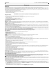
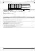
COMMUNICATOR STATUS LEDS
Table 3: Yellow Trouble Status LED
# of
Flashes
Trouble
# of
Flashes
Trouble
2 Panel Supervision Trouble 8 Receiver Supervision Trouble
4 SIM Lock Trouble 9 FTC Trouble
5 3G/GSM Trouble 10 Configuration Failure
6 Ethernet Trouble 11 Remote Programming
7 Receiver Not Available Trouble 12 Module Configuration Trouble
Table 4: Radio Signal Strength
Signal
Strength
CSQ
Level
Yellow
LED
Green
Led 2
Green
LED 1
Signal Level
dBm
Action Required
No Signal 0 ON OFF OFF -108.8
• Check all antenna connections.
• Confirm 3G/GPRS service is active in
area.
• Relocate Panel or install external
antenna.