
User's Manual


Keypad Data Display 3G Alarm Communicator Installlation Manual
8
b. Observe that the Communicator’s red and yellow LEDs are flashing together while it initializes. The red and yellow LEDs will continue to flash until the
Communicator has successfully communicated to all programmed receivers. If this is the first time the Communicator has been powered up in the panel,
the module will initiate communication to Connect24 to request remote programming.
NOTE: Initialization may take several minutes to complete. red and yellow LEDs will flash together during initialization. Do not continue to next step until the red
and yellow LEDs have stopped flashing. (If only the yellow LED is flashing, there is a Communicator trouble and the Green LEDs are not valid for Communicator
Placement Test). Correct trouble indicated by flashes on yellow LED before continuing. (See Table 5 for troubleshooting assistance).
8. 3G2060R/TL2603GR only: Perform the Communicator Placement Test below.
9. Mount the Panel in final location indicated by placement test.
Domain Name Service (DNS) programming is not permitted in UL/ULC listed systems.
Keypad Data Display
NOTE: Programming locations accessible via the keypad are for viewing only. All communicator programming is modified via Connect24.
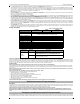
• Section-Toggle Options: The number is displayed when Toggle is ON, the number is not displayed when Toggle is OFF. (e.g., Toggle Options displays: [
--
3
--
6
--
]. Options 3 and 6 are ON, all others are OFF). Pressing keys 1 through 8 will alternately turn the Toggle ON and OFF.
• HEX/Decimal Data: Values that are provided with two defaults, separated by a “/” character, use the format: hexadecimal followed by decimal equivalent
(e.g., Default [0BF5/3061]). Hexadecimal numbers are shown, with all leading zeroes, to the full field length defined for the number.
Entering HEX values at keypad
To enter HEX values at the keypad, you must press the
*
key before entering the HEX value. (e.g., to enter “
C
” at the keypad, press
[*][3]
.
Entering ASCII Characters at keypad
1. Press [*] and use scroll buttons [<] [>] to display “ASCII Entry” on the LCD screen.
2. Press [*] to select ASCII entry mode.
3. Use the [<] [>] scroll keys to display the character you want and press [*] to save and exit ASCII.
4. Repeat the steps above to enter another ASCII character.
PC1616/1832/1864 Initial Programming
Perform the following steps to ensure that the Communicator and the Panel work together as intended.
These Sections must be programmed at the panel keypad. Enter
[*][8][Installer Code][Section Number]
. Record any values that are modified from their default,
in the appropriate Worksheets for the Panel or Communicator.
1. In Panel Section [167] program 060 (seconds).
2. In Panel Section [382] set Option [5] ON
NOTE: I
f this option is OFF, the yellow status LED on the Communicator will indicate ‘Panel Supervision Trouble’ (2 flashes) and the unit can not be programmed via the
PC-LINK cable.
3. In Panel Section [383] set Option [7] ON.
4. In Panel Section [383] set Option [8] ON for CID, or OFF for SIA.
5. A valid Account Number must be entered in Communicator Section [851][021]. See Programming Section.
NOTE: DSC recommends using the same Account Number for Panel and Communicator.
6. In Panel Sections [301], [302], and [303], program the central station telephone number that will be used for the 3G/GPRS/Ethernet Communicator. Valid
entries are:
a. A valid telephone number; signals will be routed to the central station using the PSTN.
b. DCAA (Receiver 0); signals will be routed to 3G/GPRS/Ethernet Receivers 1 - 4 depending on programming Toggle Options in Communicator Section
[851][006].
c. Panel Section [301] sets the Primary communication path, and may be configured as either PSTN or Communicator routing. Panel Section [302] is
redundant, and Panel Section [303] is the backup telephone number for Panel Section [301]. Refer to the Panel manual for additional information.
NOTE: The leading digit ‘D’ (dial tone detection) in the telephone number is pre-programmed.
7. In Panel Section [350], program the communication format as: CID (03) or SIA FSK (04).
NOTE: If any of the Panel telephone numbers have been set to DCAA, section [350] must be set to (04).
8. In Panel Sections [351] - [376], program the Communicator call direction options. Refer to the Panel Installation Manual for details on setting these options.
9. In Panel Section [401] set Toggle Option [2] ‘User Enable DLS’ to ON in order to perform panel DLS session through 3G/GPRS or Ethernet.
NOTE: Before leaving the premises, the installer should verify all programmed communications paths. See Programming Options Section
[851][901] to send immediate test transmissions.
Communicator Troubles displayed on a PC1616/1832/1864
The General System trouble is the only trouble that will appear on the keypad Liquid Crystal Display (LCD) when encountered by a Communicator installed in
a PC1616/1832/1864. For more information about the trouble on the Communicator module refer to the panel event buffer. Log entry will show Fault or
Restore for each of the following events:
• T-LINK Network Fault/Restore: This log will occur for the following trouble conditions: SIM Lock Trouble, 3G/GSM Trouble, Ethernet Trouble, or
Connect24 Configuration Trouble.
• T-LINK Receiver Trouble/Restore: This log will occur for the following trouble conditions: Receiver Not Available Trouble, Receiver Supervision Trouble,
or Failure to Communicate (FTC) Trouble.
• T-LINK Comm. Fault/Restore: This log will occur when the panel loses communications with the Communicator and will clear when communications is
restored.
(3G2060R and TL2603GR only).
To confirm that the 3G/GPRS antenna location is suitable for radio operation, perform the placement test as follows:
NOTE: You may need to relocate the Panel or install an optional extension antenna during this procedure, if radio signal strength is too low.
1. Confirm that the yellow LED on the Communicator is not flashing. A flashing yellow LED indicates trouble on the Communicator. See Table 5 to trouble-
shoot and correct the cause of this trouble before continuing to the next step.
2. Observe the strength of the radio signal on the yellow LED and the 2 green LEDs on the Communicator meet or exceed the minimum signal level requirement.
Minimum Signal Level: The yellow LED is OFF and the Green LED 1 (furthest from the yellow LED) is ON. (i.e., not flashing) for the panel location to be accept-
able. See table for “Radio Signal Strength” on page 9 for interpretation of receiver signal strength on LEDs.
NOTE: If the required signal strength is too low with the panel in its current location, the panel must be relocated or an external antenna is
required.
a. If required, the following 3G/GSM extension antenna kits are available to the installer:
•GS15-ANTQ - 4.57m (15’)Internal Antenna Extension Kit (Suitable for interior mounting only).
•GS25-ANTQ - 7.62m (25’)External Antenna Extension Kit (Suitable for exterior mounting only).
•GS50-ANTQ - 15.24m (50’)External Antenna Extension Kit (Suitable for exterior mounting only).
Specific instructions for the installation of the extension antenna are included with the kit. Observe all the electrical safety instructions regarding the installation
of the antenna. All the wiring of the equipment shall be fully compliant with the local rules and regulations.
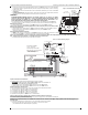
3. If required, install the antenna extension and perform the following steps to determine the best location for placement of the antenna :
a. Disconnect the white whip antenna from the panel.
b. Attach one end of the antenna extension cable to the threaded antenna connector on the panel and the other end to the external antenna.
4. Move the extension antenna to various locations while observing the two Green LEDs on the panel.
a. Continue to reposition the extension antenna until you receive an acceptable (minimum one green LED ON solid) signal strength.
NOTE: Minimum strength is: green LED 1 flashing and yellow LED OFF. If green LED 1 is flashing, relocation should be considered.
b. Mount the supplied antenna extension bracket at the location that provides the best signal strength.
INITIAL PANEL PROGRAMMING
COMMUNICATOR PLACEMENT TEST