
User's Manual


3G Alarm Communicator Installlation Manual Installing Communicator with PC1616/1832/1864 Panel
7
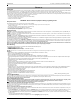
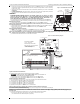
e. Locate the screw hole on the right side wall of the panel. See Figure 2 (screw). Line up the assembled
Communicator with the right side wall of the panel and, using the screw provided, secure the mounting
bracket to the panel.
f. Attach the other end of the PC-LINK cable to the Communicator (black wire goes on Pin 1 of the Com-
municator).
g. TL260R/TL2603GR only: Using light pressure (finger tight only), attach the supplied white quad band
whip antenna to the threaded antenna connection point at top of the panel.
WARNING!
3G2060R/TL260R/TL2603GR MODULES ARE POWER LIMITED. DO NOT ROUTE ANY WIRING
OVER
THE CIRCUIT BOARD. MAINTAIN AT LEAST 1IN. (25.4MM) SEPARATION BETWEEN CIRCUIT
BOARD
AND WIRING. A MINIMUM OF ¼ IN. (7MM) SEPARATION MUST BE MAINTAINED AT ALL
POINTS
BETWEEN NON-POWER LIMITED WIRING AND POWER LIMITED WIRING.
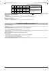
3.To electrically connect the Communicator to the panel, perform the following steps (See Figure 3).
a. Disconnect both AC power and battery connections from the panel, and disconnect telephone line.
Module Power Connection
b. Attach a wire from the Communicator’s left PWR terminal to the panel’s BELL+ terminal.
NOTE: For ULC Commercial Fire Monitoring applications, do NOT connect any devices on the Bell + terminal
other than the Communicator.
c. Attach a wire from the Communicator’s GND terminal (beside PWR) to the panel’s AUX - terminal.
d. Attach a wire from the Communicator’s SHLD terminal to the panel’s EGND terminal.
(Protective earth ground).
(Optional) External Bell/Siren Connection
e. Attach a wire from the Communicator’s right PWR terminal to the positive (+) terminal on the Bell/
Siren.
f. Attach the panel’s BELL
-
terminal to the negative (
-
) terminal on the Bell/Siren.
NOTE: If an external Bell/Siren is not used, install the 1K
½W 5% resistor (Brown, Black, Red, Gold) (supplied with the panel) between the panel’s Bell + and
Bell
-
terminals, then only wire the BELL + to the PWR terminal on the Communicator.
g. Confirm that the SIM card is inserted in the holder and locked.
Keybus Connection for C24 Interactive
4. Install the Keybus cable between Communicator and Panel as follows:
WARNING: DO NOT CONNECT KEYBUS RED OR BLK WIRES TO THE PANEL OR
THE COMMUNICATOR TERMINAL BLOCKS.
a. Attach a wire from the Communicator YEL terminal to the panel YEL terminal.
b. Attach a wire from the Communicator GRN terminal to the panel GRN terminal.
RS-422 Connection for C24 Interactive
At the Communicator inside the Panel, connect the previously run RS-422 cable as follows:
1. Securely fasten the TX+ wire to RX+ on the terminal block.
2. Securely fasten the TX- wire to RX- on the terminal block.
3. Securely fasten the RX+ wire to TX+ on the terminal block.
4. Securely fasten the RX- wire to TX- on the terminal block.
5. (Optional) Securely fasten the GND wire on the terminal block.
NOTE: The GND connection is optional. DSC recommends connecting GND wire at both ends.
Install Network Cable (TL260R/TL2603GR only)
6. Route the CAT 5 Ethernet cable through back of the panel and plug it into the Communicator’s RJ45 jack.
Before leaving the premises the Ethernet communication lines must first be connected to an approved (acceptable to local authorities) type NID, (UL
installations, UL 60950 listed NID, for ULC installations CAN/CSA C22.2. No. 60950-1 Certified NID). All wiring shall be performed according to the local
electrical codes.
7. Perform the following steps for initial power on of the panel with Communicator installed:
a. Reconnect the AC power, telephone line, and battery + connector to the panel.
(The Communicator and Panel will power up together).
DG009545
PC-Link
Cable Connector
(screw)
Quad band
Whip Antenna
PC1616/1832/1864
GSM Radio
RJ-45
UA585
Use light pressure
to attach antenna
Finger Tight only.
Figure 2 PC1616/1832/1864 Control Panel
Figure 3 Communicator Wiring Diagram
AUDIO/DEFAULT
DSC
UA601
PC-LINK
PC-LINK
COM
TL260(R)
TL2603G(R)
3G2060(R)
AC
AC
Z1 COM Z2 Z3 COM Z4 Z5 COM Z6 Z7 COM Z8
AUX+
BELL +
PGM1 PGM3
RING
T-1
PC1616/1832/1864
3G Radio
+
-
UA503
1
To external antenna
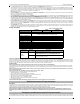
Input Ratings from Bell +:
+11.1V ~ +12.6 VDC
100mA standby; 400mA alarm
DSC Panel min. power requirements:
- 16 VAC 40 VA transformer;
- 12 VDC 7Ah battery
+
-
External Bell/Siren
Black
Black
Jumper pins 4 and 5
to reset.
L
o
c
k
1
GRN
RS-422
To
C24-HUB
Maximum cable length 305 m (1,000 ft)
From NID
TL2603G(R) / TL260(R)
Use only CAT5
Supervised
RJ-45
YEL
COM
PWR
GRN
YEL
TIP
R-1
BLK
RED
AUX -
BELL -
EGND
Do NOT
connect
Red or Black
Keybus wires!
TX+
GND
TX-
RX+
RX-
SHLD
Green
Yellow
SIM
Network Link
YELLOW
XX
PGM2 PGM4
Maximum cable length
100 m (328 ft)
PWR
DG0009745